Superstructure of a submarine. Trends in the development of submarine architecture. Bulwark and railing
Series VII submarines were easy-to-manufacture one-and-a-half-hull boats. Side boules, bow and stern ends and deck superstructure. The diameter of the pressure hull in the area of the central post was only 4.7 meters. The thickness was 16 mm at the ends 18.5 mm in the center, and together with the connections to the deckhouse it was 22 mm. On the C/41 modification, the thickness increased to 18.5 mm at the ends and to 21.5 mm in the central part.
The durable hull of these submarines could withstand not only the outboard water pressure, but also the fire of machine guns and small-caliber cannons of ships and aircraft. In post-war tests of captured boats, it turned out that 20, 23 mm shells and 37 mm incendiary fragmentation shells caused damage only to the light hull. Also, because of this, the Allies observed problems when trying to ram the submarine. There is a known case when an American destroyer Borie Having rammed the submarine, U-405 received severe damage and was sunk by its own aircraft.
The durable body was welded from eight sections, six of them were sheets of metal, bent and welded into cylinders. The bow and stern sections were welded from three sheets of metal. The sections were sequentially welded to each other, then the deckhouse was welded to them. A fairly large hole was left behind it, through which instruments and mechanisms were loaded into the boat.
The latest to be installed were diesel engines. After installing them, the hole was welded with a steel sheet. This made it clear that the boat was not designed for long-term operation; the destruction of the submarine was expected earlier than the time it was put on average for repairs. Type VII was divided into six compartments. The central post was separated from the concavity side by spherical bulkheads designed for a pressure of 10 atm; it could serve as a shelter compartment.
Placement of instruments and mechanisms in the compartments:
1st compartment (bow torpedo)
This compartment housed four torpedo tubes. two in vertical rows and a supply of six torpedoes. Four were stored under the deck deck and two along the side. For loading and loading torpedoes, the boat had special internal transport and loading devices. Also, along each side there were three pairs of folding, two-tier bunks. At the bottom of the compartment, under the spare torpedoes, there were bow trim and torpedo replacement tanks, as well as a manual control drive for the bow horizontal rudders.
2nd compartment (bow accommodation)
The compartment was divided into two parts by a thin bulkhead and a door. The room located closer to the bow was small; it housed a latrine and places for four sergeants. Next came the officer's quarters with two bunks in two tiers on each side. At the bulkhead of the central post, on the left side there was a captain's berth, separated from the aisle by a curtain. Since it was very small, the only furniture it contained was the bed itself, a folding table, a cabinet built into the wall.
On the starboard side of the boat, opposite the captain’s seat, there were sonar and radio operator posts. Under the deck flooring there was a bow battery group (consisting of 62 elements), air cylinders high pressure and an artillery cellar.
3rd compartment (central post)
The anti-aircraft periscope was located here, the commander's was located higher in the conning tower. Also, control posts for kingston valves and ventilation, drives remote control horizontal rudders. Here was the navigator's combat post. The largest mechanisms in this compartment are two pumps and a hydraulic motor that raised the periscopes.
Along the sides there were tanks with drinking water and hydraulic oil. An equal-strength ballast tank of large volume was located under the central post, it played the role middle group. Fuel tanks are located on both sides of it. Above the central post, in the narrow conning tower, there was the commander’s combat position during a torpedo attack - a folding seat (rotated along with the commander’s periscope), a PSA (counting and solving device) for controlling torpedo firing.
4th compartment (aft accommodation)
In the jargon of submariners it was called "Potsdamer Platz" because of the prevailing noise, din and running around, since this compartment connected the galley, diesel and electric motor compartments with each other. Also in the compartment there were beds for four non-commissioned officers, a second latrine and a second power station. Under the deck flooring there was a second group of batteries, high-pressure air cylinders and a fuel tank.
5th compartment (diesel)
Almost the entire compartment above the deck flooring was occupied by two huge diesel engines. Also here, there were cylinders with compressed air for starting engines and a cylinder with carbon dioxide for extinguishing fires. At the bottom of the compartment under the diesel engines there were oil tanks.
6th compartment (electric motor and stern torpedo)
The compartment housed two high-pressure air compressors, diesel on the starboard side, electric on the left. There were two electric motors, a stern torpedo tube, power and manual control posts for horizontal rudders. Under the deck flooring, between the electric motors, there was a spare torpedo; closer to the stern, there was a trim and torpedo replacement tank. There was a hatch in the roof of the compartment for loading torpedoes. At the end of the war, a device similar to a torpedo tube, but inferior in size, appeared in the compartment; it was intended for the release of imitation Bold cartridges.
Superstructure
Inside the light hull and superstructure there were systems and mechanisms, the most important of which were hydrophones, a capstan device, an anchor, four waterproof cases for inflatable rafts, camouflage nets, two cases for storing spare torpedoes (one case was closer to the bow, the other closer to the stern , they could store G7a torpedoes). There were waterproof fenders for the first shots for the 88 mm deck gun, an air supply shaft for the diesel engines, exhaust valves and diesel mufflers, and most of the high-pressure air system cylinders.
The deck of the superstructure was made of wooden planks, since wood matured later than iron. The deckhouse fence was used to accommodate anti-aircraft guns, numerous movable and fixed devices, as well as for watchkeeping. Behind, inside the fence, there was an air intake for the air supply shaft to diesel engines and fenders for the first shots for anti-aircraft guns.
Dive and ascent system
The main ballast of the boat consisted of five tanks. The first and fifth tanks were located in a light hull, the fifth tank was in the bow, there was also a quick submersion tank, and the first tank was located in the aft end, the second and fourth tanks were in the side bulges, the third tank was in the durable hull of the 3rd compartment. All tanks, except the first and third, could be filled with fuel.
In addition to the middle group, the main ballast tanks were kingless, and the valve control was located at the central station of the boat. Between the second and fourth tanks, there were two small fuel and ballast tanks, a surge tank and an onboard buoyancy tank. The VVD system was assembled from steel pipes and was not designed for long-term use.
The total volume of VVD cylinders is 3.46 m³, since 1944 the volume has been 5.2 m³. The compressed air was under a pressure of 295 kg/cm². To replenish compressed air supplies there were two 6-liter compressors - diesel and electric. Two pumps were part of the drainage and trim systems, with a capacity of 30 and 18 tons, respectively.
At a signal, the top watch personnel jumped into the wheelhouse and battened down the hatch, the watchmen of the central post shifted the horizontal rudders to dive and opened the ventilation valves of the main ballast tanks from bow to stern. The well-thought-out shape of the horizontal rudders allowed German boats to dive with a large trim on the bow and not be afraid to make a somersault.
To speed up the dive, “live” ballast was used; the entire crew of the boat, free from watch duty, had to run to the bow compartment. These actions were practiced both during the introductory combat training course and during combat campaigns. Within 25-27 seconds, a trained crew could take the boat to a depth of 10 meters.
Power plant
The power plant of the Type VII submarines consisted of two six-cylinder four-stroke diesel engines F46, which were installed on most boats, or MAH M6V 40/46 engines with mechanical supercharging. Engine power on modifications A was 1169 hp, on all other modifications 1400 hp. Maximum speed the speed on diesel engines was 16.9 knots; when running on diesel engines with electric motors, the speed was 17.4 knots.
In the summer of 1943, due to Allied aviation, German submarine operations in the Atlantic were stopped. In February 1944, after repairs, U-264, the first German Type VII submarine equipped with a snorkel, entered service. The snorkel itself consisted of the following: two pipelines from the diesel compartment were connected in the bow of the wheelhouse to a special folding mast; at the end of this mast there was a valve for air intake and exhaust gas release from diesel engines. The design of the valve provided for its automatic closing when water entered, but the diesel engines did not stop and took air from the internal compartments of the boat, this could create a large vacuum in a closed environment.
Despite the difficulties in operation, the snorkel was a device thanks to which the boat, in a submerged position, fully charged its battery in three hours at a speed of 3-4 knots. Every 20 minutes, the underwater passage using a snorkel and diesel engine was stopped and a hydroacoustic search was carried out.
Typically, electric motors were used to move underwater. The Type VII boats had two twin-anchor electric motors from the company Siemens , A.G. or Brown Boweri with a power of 375 hp As on Soviet submarines, electric motors and diesel engines were connected to the propeller shaft by mechanical couplings. Battery 124 cells types 27-MAK 800, later 33-MAL 800W. The ventilation of the elements is individual, the flooring of the pits is hermetic.
The normal supply of fuel in the internal tanks was 62.14 tons, the total supply in the fuel and fuel-ballast tanks was 105.3 tons, when the surge tank was filled with fuel, it was 113.47 tons. The supply of fresh water on board the boat was 3.8 tons, oil 6 tons, and oxygen - 50 liters. The endurance of Type VII submarines is approximately 40 days. The cruising range at a speed of 10 knots is 8500 miles; with diesel-electric transmission, the range increases to 9700 miles. The diving range depended on the type of batteries, 130 miles at 2 knots or 80 miles at 4 knots.
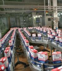
A deck boat is a relatively new type of pleasure craft that receives last years increasingly widespread in countries with warm, sunny summers. This is the development of the so-called pontoon vessels, which are a platform mounted on two pontoon floats - a welded structure made of aluminum alloys or molded from fiberglass. An uncluttered, rectangular, stable platform, fenced along the perimeter with reliable railings and a low bulwark, creates the illusion for passengers of a pontoon boat of being in a familiar coastal environment: there is no cramped cockpit and rooms, which is typical for small vessels. Thanks to the large deck area, such boats are very convenient for Sunday walks with the whole family or picnics for up to eight people. Pontoon boats are usually equipped standard sets furniture (sometimes - a folding summer cottage set) and only a light sun awning, since they are not designed for long-term stay of passengers away from the shore in bad weather(if it gets colder or rains, they usually return to the parking lot at full speed).
Pontoon boats, due to their simplicity of design (the pontoons themselves are most often cylindrical pipes with a diameter of 450-600 mm), are relatively cheap. When disassembled, they can be easily delivered to isolated reservoirs. However, such boats also have a number of disadvantages. First of all, this is a limited navigation area: they can only be sailed along relatively quiet rivers, lakes and well-closed sea bays: it is difficult for a low-sided boat with a developed sail to withstand large waves and strong winds. The planing working area of narrow pontoons in the stern is limited, and this does not allow installing an engine powerful enough to develop high speed. There is no hold, the volume of which could be used for stowing equipment and supplies.
Boat basic data
Apparently, the desire to maintain “spaciousness” and “freedom of flexible layout” on the deck, but to get rid of these shortcomings, prompted a number of firms in the West to develop and put into production a new type of vessel, called deck boat. In this version, the hull is most often given trimarain contours, which preserve the almost rectangular outline of the deck and ensure high stability of the boat. The high-sided hull of a wide trimaran motorboat has higher seaworthiness than wave-rolled pontoons; it can install a stationary engine of significant power and enclose spaces for storing luggage. There is no traditional cockpit; the hull is covered by a deck, the entire area of which is used to comfortably accommodate passengers in the same way as on a pontoon boat. The photo shows one version of a typical high-speed deck boat, equipped with a 140-horsepower Mercruiser sterndrive engine.
An interesting version of a deck boat, adapted for river travel, was developed by the famous designer of small boats, David Beach from Chicago (three of his projects - the motor-sailing yacht "Dolphin", a boat with plywood sheathing and a round-billed floating boat were published in, and collections, respectively).
The project, designed specifically for self-construction, was awarded 2nd prize at an international competition organized by the OMS engine-building concern with the aim of expanding the scope of application of the Zephyr stationary installation with an outboard motor engine ().
The design of the hull is designed to be covered with waterproof plywood (aircraft plywood 8 mm thick or bakelized plywood 7 mm thick can be used) over tight frames (600 mm spacing) and longitudinal stringers made of pine slats. The designer provided for the possibility of operating the boat with one Zephyr installation with a capacity of 15 hp. s., as well as with any other engine or outboard motor in a fairly wide power range - up to 140 hp. With. The simplified flat-keeled hull contours are adapted for economical sailing in displacement mode at the lower power limit, and for planing with an engine power of over 60 hp. With. In the attached drawings you can see the rise of the bottom upward at the transom to reduce water resistance at low speeds and a decrease in the deadrise of the bottom towards the stern to facilitate the vessel's entry into planing mode. The developed keel fin protects the propeller from damage when running aground and prevents the ship from drifting in cross winds.
The boat is designed to be towed on a trailer behind a passenger car, which, by American standards, limits the hull's overall beam to 8 feet (2.43 m). The main part of the deck area is occupied by a shallow (its bottom is 200 mm higher than the waterline) self-draining cockpit, the dimensions of which in plan are 2.08X1.54 m. These three square meters can be used depending on the circumstances and the desire of the crew. For example, you can lay out a couple of air mattresses here and arrange a solarium, or sit down for lunch on folding chairs. It is important that even while underway, passengers in the cockpit are reliably protected from wind and splashes: from the bow and stern - by short and high superstructures, which give the boat such an unusual look, and from the sides - by low bulwarks. A light tubular frame (collapsible design) between the superstructures serves as the basis for a solar awning, but in bad weather or, say, when mosquitoes appear, fabric sidewalls can be fastened to this awning and you will get a cozy cabin with an inside height of 1.9 m. For an overnight stay in it - again on air mattresses - can accommodate 3-4 people. The cockpit platform is equipped with outboard scuppers to drain any water that gets there.
The superstructures play the role of utility rooms. In the stern there is a sink and gas stove, as well as a toilet with a removable tank (a device required on board pleasure boats according to the rules of most states). This superstructure can be entered from both the deck and the cockpit via sliding doors. Indoor height 1.83 m; in its upper part there is a niche for laying pipes and awning panels.
There is glass attached to the bow superstructure, protecting passengers from headwinds and allowing forward visibility. Inside there are lockers for clothes and various camping equipment. The boat control panel is attached to the front wall on the console. The driver and one of the passengers are located in comfortable chairs right on the foredeck. The steering wheel is mounted on a reversible console, which rotates in a vertical plane in such a way that any of the people sitting here can control the boat.
The voluminous forepeak serves as a storage room, and to facilitate its use, two hatches are equipped on the deck. A wide double hatch at the stern provides access to the engine compartment, where one or two Zephyrs or another stationary engine can be installed. Fuel tanks are also located here. In addition to the cockpit, a fairly large free deck area is preserved: the covers of all hatches are made “hidden”, there are passages along the boat along the side footpaths.
In general, an amateur boater who has built such a boat will have at his disposal a fairly comfortable floating cottage, suitable for both Sunday relaxation and longer family voyages.
In our conditions, instead of the Zephyr installation, an outboard motor mounted in the usual way on the transom (it is also worth equipping an under-engine niche) or installed permanently in the engine compartment (see the book “Boats, boats and motors in questions and answers.” L., “Shipbuilding”, 1977). Considering the relatively low speed of movement with moderate power of 20-25 hp. pp., it is useful to use a propeller with a smaller pitch and a ring-profiled nozzle, which significantly increases the efficiency of the propulsion unit.
This section is written based on materials taken from the site http://randewy.narod.ru/nk/pl.html"Online club for a young sailor", and is intended to give a general idea of the design and structure submarines. Although the illustrations date back to the mid-twentieth century, they nevertheless give an idea of the design of modern submarines, which differ from those shown in the drawings, first of all, in their size and shape, adapted for swimming under water, and not for swimming on the surface and “diving” “, as was the case before the advent of nuclear submarines and developed anti-submarine defense.
Submarines can be of one of three architectural and structural types. The figure above shows cross sections of boats of various architectural and structural types (the numbers indicate: 1 - strong hull, 2 - superstructure, 3 - fencing of the wheelhouse and retractable devices, 4 - strong deckhouse, 5 - main ballast tanks, 6 - light hull; 7 - keel; the meaning of these terms is explained further in the text ):
single-hull(s), having a “bare” durable hull, which ends at the bow and stern with well-streamlined ends of a lightweight structure;
one-and-a-half-hull (b), having, in addition to a durable body, also a lightweight one, but part of the surface of the durable body remains open;
double-hulled (in), having two housings: internal - lasting and external - easy. At the same time, the lightweight hull has a streamlined shape, completely envelops the robust hull and extends the entire length of the boat. The inter-hull space is used to accommodate various equipment and parts of tanks.
Submarines of the USSR and Russia are double-hulled. Most US nuclear submarines (they haven't built diesel-electric ones since the early 1960s) are single-hulled. This is an expression of the top priority for naval strategists of various qualities: surface unsinkability for the USSR and Russia and stealth for the USA.
Rugged housing- the main structural element of a submarine, ensuring its safe stay at depth. It forms a closed volume, impenetrable to water. Inside the durable hull there are premises for personnel, main and auxiliary mechanisms, weapons, various systems and devices, batteries, various supplies, etc. Its internal space is divided along the length by transverse waterproof bulkheads into compartments, which are named depending on the purpose and, accordingly, the nature of the weapons and equipment housed in them.
In the vertical direction, the compartments are separated by decks (stretching along the entire length of the boat's hull from compartment to compartment) and platforms (within one compartment or several compartments). Accordingly, the boat’s premises have a multi-tier arrangement, which increases the amount of equipment per unit volume of the compartments. The distance between decks (platforms) “in the clear” is more than 2 m, i.e. slightly larger than the average human height.
The structurally sound hull consists of frames and plating. The frames, as a rule, have a circular annular shape, and at the ends they can have an elliptical shape and are made of profile steel. They are installed one from another at a distance of 300 - 700 mm, depending on the design of the boat, both on the inner and outer sides of the hull, and sometimes in combination on both sides.
The casing of the durable hull is made of special rolled sheet steel and welded to the frames. The thickness of the skin sheets reaches 35 - 40 mm, depending on the diameter of the pressure hull and the maximum immersion depth of the submarine.
Pressurized hull bulkheads are strong and lightweight.
Bulkheads divide the internal volume of modern submarines into 6 - 10 waterproof compartments. Strong bulkheads They fence off shelter compartments in it, in which the crew members who survived the accident can prepare to independently ascend from the sunken boat to the surface or wait for outside help. By location, strong bulkheads are internal and end; in shape - flat and spherical (spherical ones are somewhat lighter than flat ones with the same strength and the internal spherical bulkheads are convexly facing the shelter compartments).
Light Bulkheads are designed to separate functionally specialized rooms and ensure the surface unsinkability of the ship (i.e., when the compartments are flooded, they withstand water pressure only if the boat is on the surface or at a depth within 20 - 30 m).
Structurally, bulkheads are made of frames and sheathing. A bulkhead set usually consists of several vertical and transverse posts (beams). The casing is made of sheet steel.
The end waterproof bulkheads of the durable hull are of equal strength and close it at the bow and stern ends. These bulkheads serve on most submarines as rigid supports for torpedo tubes, shafting, steering gear drives, set mountings, and internal structures of light ends.
The compartments communicate with each other through waterproof doors having a round or rectangular shape. These doors are equipped with quick-release locking devices.
In the upper part of the strong hull, a strong wheelhouse is installed, communicating through the lower wheelhouse hatch with the central post (inside the strong hull) and through the upper wheelhouse hatch with the navigation bridge (in the upper part of the wheelhouse fencing and retractable devices - periscopes, antennas). On most modern submarines, the strong deckhouse is made in the form of a round cylinder with a vertical axis or is a combination of a cylindrical part and truncated cones. On some boats, the robust deckhouse is designed so that it can be used as a pop-up rescue chamber, the purpose of which is to evacuate the entire crew or some part of it (which after the accident retained the ability to access the central control room and the pop-up camera) from a dying or sunken submarine.
Currently, on most boats, the main purpose of a strong deckhouse is to place the entrance to the strong hull as high as possible above the surface of the water when sailing on the surface. In addition, since the central post on many boats is one of the shelter compartments, the strong deckhouse is designed to serve as an airlock when people exit a sunken boat.
On the outside, the strong wheelhouse and the retractable devices located behind it, to improve flow around when moving in a submerged position, are covered with lightweight structures called the wheelhouse fencing or the retractable device fencing. At the top of the fence there is a navigation bridge with a full set of devices necessary to control the boat on the surface and means of communication with the central post. From the wheelhouse enclosure there are exits to the upper deck (in fact, the entrance to the strong hull through the hatches of the strong wheelhouse is the main one, since the hatches in the strong hull are prescribed by the boat operating manual to be kept closed in most cases).
The torpedo-loading and access hatches are located in the upper part of the durable hull and are covered on top with lightweight structures called superstructure. In most cases, these hatches are located in shelter compartments and are rescue hatches, for which purpose they are equipped with locking devices. The superstructure also contains devices designed for mooring, towing the boat and ensuring its anchorage.
Tanks designed for immersion, ascent, signboarding and trimming the boat, as well as for storing liquid cargo (fuel, oils, etc.). Depending on their purpose, tanks are divided into tanks: main ballast, auxiliary ballast, ship stores and special. Structurally, depending on the purpose and nature of use, they are either durable, i.e. designed for the maximum depth of immersion, or light, capable of withstanding pressure of 1 - 3 kg/cm 2 (kg is an off-system unit, a kilogram of force, equal to the weight of 1 kg of mass with a free fall acceleration of 9.81 m/s 2). They can be located inside the strong hull, as well as in the space between the strong and light hull in the middle part of the ship and in the light ends fore and aft of the strong hull.
Keel- a welded (formerly riveted) beam of box-shaped, trapezoidal, T-shaped, and sometimes semi-cylindrical section, located in the bottom of the boat hull. It is designed to provide longitudinal strength, protect the hull from damage when placed on rocky ground, and to accept and redistribute the load when docking the boat. It can be located in the space between the hulls on double-hull boats, and on one-and-a-half and single-hull boats it can be located both inside the durable hull and outside - depending on what is more important for the customer - good hydrodynamics or protection of the durable hull from mechanical damage if the boat is in for certain tactical purposes they are placed on the ground.
Lightweight body- structurally includes a rigid frame (set), consisting of frames (transverse stiffeners), stringers (longitudinal stiffeners and plate elements of the set), transverse impenetrable bulkheads; the frame is the carrier of the light hull skin. Structurally, the light body kit is connected to a durable body located inside it. The lightweight hull has a streamlined shape that provides the necessary seaworthiness both on the surface and in the submerged position. The light hull is divided into parts: the outer hull, the bow and stern ends, and the superstructure. At the same time, it contains both permeable and impermeable structures (tanks). In addition to the light hull, the design of the boat includes separate, mostly permeable, structural elements: the deckhouse fencing, stabilizers, fairings of various kinds of devices located outside the durable hull and extending beyond the contours of the “ideal” shapes of the light hull.
The outer hull is the waterproof part of the lightweight hull located along the durable hull. It encloses the pressure hull along the perimeter of the boat's cross-section from the keel to the top watertight stringer and extends the length of the ship from the fore to aft end bulkheads of the pressure hull or main ballast tanks. Some boats have an ice belt, which is a thickening of the skin of a light hull in the area of the cruising waterline.
The ends of the light hull serve to streamline the contours of the bow and stern of the submarine; extend from the end bulkheads of the pressure hull to the stem (at the bow) and the sternpost (at the stern), respectively. However, boats (primarily nuclear-powered, which spend most of their voyages underwater) can have a teardrop-shaped hull without a stem or sternpost (the stem and sternpost are vertical stiffening ribs as part of the ship’s hull, giving a sharpness to the bow and stern, respectively, which is necessary to reduce resistance of water when floating on the surface).
The bow end houses: bow torpedo tubes, main ballast and buoyancy tanks, a chain box, an anchor device, receivers and emitters of the main hydroacoustic stations.
The aft end houses: main ballast tanks, horizontal and vertical rudders, stabilizers, propeller shafts and propellers. Some boats have stern torpedo tubes (most modern boats do not have stern torpedo tubes: this is primarily due to the large size of the propellers and stabilizers, as well as the fact that torpedo control algorithms allow them to be placed on almost any course, regardless of direction of the shot).
Below is a longitudinal section of a diesel-electric submarine from the mid-twentieth century, with an explanation of the design elements and devices. (A longitudinal section of the Kursk nuclear submarine with explanations is presented in Fig. 5 in Chapter 6).
1. Durable body. 2. Bow torpedo tubes. 3. Lightweight body. 4. Bow torpedo compartment. 5. Torpedo loading hatch. 6. Superstructure. 7. Durable cutting. 8. Cabin fencing. 9. Retractable devices. 10. Entrance hatch. 11. Stern torpedo tubes. 12. Aft end. 13. Rudder feather. 14. Aft trim tank, the purpose of which is to level the trim - the longitudinal inclination of the boat. 15. Aft watertight bulkhead. 16. Aft torpedo compartment. 17. Internal watertight bulkhead. 18. Main propulsion motors compartment. 19. Ballast tank. 20. Engine compartment. 21. Fuel tank. 22, 26. Stern and bow groups of batteries. 23, 27. Team living quarters. 24. Central post. 25. Hold of the central post. 28. Nasal trim tank. 29. Bow watertight bulkhead. 30. Nasal extremity. 31. Buoyancy tank (an attribute of some diesel-electric submarines; its purpose is to be empty when floating on the surface in order to give additional buoyancy to the bow so that the boat can easily rise to the wave, and not buried her nose in it - this reduces the speed and worsens controllability).
The following figure shows a cross-section of the deckhouse fence of a one-and-a-half-hull submarine from the mid-twentieth century, indicating the hull structural elements.
1. Navigation bridge. 2. Durable cutting. 3. Superstructure. 4. Stringer. 5. Leveling tank (designed to accurately balance the buoyancy force and weight of the boat in a submerged position). 6. Reinforcing stand (bracket). 7, 9. Brackets (plates to which the set elements are attached, they are designed to distribute the load and eliminate stress concentrations. 8. Platform. 10. Box-shaped keel. 11. Diesel foundation. 12. Sheathing of the strong hull. 13. Frames of the strong hull. 14. Main ballast tank 15. Struts (brackets) 16. Tank cover 17. Light hull plating 18. Light hull frame 19. Upper deck
Submarines of the Shch type, or, as they were also called, pikes, occupy a special place in the history of domestic shipbuilding. These were the most numerous (86 units!) medium submarines Soviet fleet period of the Great Patriotic War. They actively participated in hostilities in the Baltic, Black Sea, and Arctic; their torpedoes and artillery sank a German submarine, a patrol ship, two landing craft and at least 30 enemy transports. But the price of victory turned out to be extremely high: 31 “pike” did not return to their home base and remained at sea forever. Moreover, the circumstances of the death of many submarines are unknown to this day...
However, we will not dwell on the history of submarine service. We offer exclusive material - reconstruction appearance"pike" of all six series: III, V, V-bis, V-6hc-2, X and X-bis. The developed drawings are based on original documentation from the funds of the Central Naval Museum (TsVMM), the Russian State Archive navy(RGAVMF), as well as special literature and numerous photographs.
Despite the fact that all series of boats of the “Shch” type were quite similar in their characteristics, in appearance they differed significantly from each other. Thus, the first four submarines Shch-301 - Shch-304 (III series) had a straight stem, a narrow superstructure and a wheelhouse fence, in the aft part of which there were gratings for blowing ventilation shafts. The bow horizontal rudders were of a unique design - they “horned” in the front part into special slots in the hull. The bow gun originally had a bulwark, but immediately after testing it was removed, and the wheelhouse fence itself was completely rebuilt. For the convenience of the crew of the 45-mm gun, folding semicircular platforms were installed, and later, during the overhaul, these platforms became permanent and were equipped with a tubular railing.
On series V submarines built for the Pacific Fleet, the shape of the bow rudders was changed (it became standard for all subsequent pike series) and the width of the superstructure was increased. The wheelhouse fence was radically reconstructed, placing a second 45-mm gun on it. The stem became inclined, and its contours in the upper part formed a small “bulb”. The length of the light hull has increased by 1.5 m.
The submarines of the V-bis series differed from their predecessors only in the shape of the false keel and the fencing of the wheelhouse (the latter lost a kind of “balcony” above the first gun). But on the V-6nc-2 series, the contours of the light hull were changed and the wheelhouse fence was again redone. Moreover, Pacific boats of this type differed from the Baltic and Black Sea ones in the shape of the sides of the navigation bridge.
The X series submarines looked the most exotic due to the introduction of a streamlined wheelhouse fencing of the so-called “limousine” type. Otherwise, they were practically no different from the V-bis-2 series ships, with the exception, perhaps, of the “hump” that appeared above the deck tank and diesel mufflers.
Since the expected increase in speed underwater in the X series boats did not occur, and the flooding of the navigation bridge increased, the last series of X-bis pikes used a more traditional wheelhouse fencing, reminiscent of that designed for C-type submarines. The bow 45-mm cannon was now installed directly on the deck of the superstructure. The hull remained unchanged, but the underwater anchor disappeared from its equipment.
The racks of antennas and network outlets on boats of the III, V and V-bis series were L-shaped and connected by crossbars. The net drain cables ran from bow to stern; in front of the bow strut they were combined into one.
In the “pike” \/-bis-2 and X series, the power outlet racks became single; on the X-bis series they were absent altogether. Some of the boats were equipped with “Som” and “Crab” net cutters, which were a system of cutters (four on the stem, two on the forecastle linearly elevated and one on each side), as well as a system of guy ropes that protected the protruding parts of the boat from getting caught by net fence cables. In practice, these devices turned out to be ineffective, and they were gradually dismantled, covering the saw on the stem with metal sheets.
The exhaust openings of the mufflers in the superstructure on the boats of the first four series were located on both sides, on the submarines of the X and X-bis series - on one, left side. Only on the left side was there an anchor, which was used in the surface position.
The location of scuppers in the superstructure, which is often an individual feature of the ship and therefore of particular interest to modellers, is, as a rule, not indicated on design drawings (since it is not of fundamental importance). In the proposed drawings of the pikes, the scuppers are drawn from photographs and therefore their location may not be entirely accurate (this especially applies to the Shch-108). It should also be borne in mind that the cutting of scuppers on boats of the same series often differed greatly; These differences are most clearly demonstrated by the Baltic and Black Sea “pikes” of the X series.
The appearance of the Shch type submarines also changed due to modernizations carried out during the service. Thus, the folding parts of the gun platforms were gradually replaced by permanent ones and equipped with railings. Based on the experience of sailing in broken ice and in fresh weather, the outer covers of the torpedo tubes were removed from some of the boats. Instead of a second gun, a DShK machine gun was sometimes installed, and the Pacific Fleet had homemade installations, along with a standard pedestal one. External 7.62-mm M-1 (Maxim) machine guns were not always placed in their standard places on the surface. The emitters of the underwater communication installation were located on the deck (upper) and in a special enclosure (lower). During the war, some pikes received Asdik sonars (Dragon -129) and a demagnetizing device with windings outside the hull at the level of the superstructure deck.
Coloring: the hull and superstructure of the Baltic boats above the waterline were gray-spherical, those of the Black Sea were dark gray, and those of the North Sea were gray-green. The underwater part is black (kuzbasslak) or coated with anti-fouling compounds No. 1 and 2 (dark red and dark green). IN besieged Leningrad In addition to camouflage nets, they used to paint the boats white to match the snow background. The screws are bronze. Rescue buoys were painted in the color of the hull; after the war they became red and white (three sectors of each color). The letters of the boat names in the bow (on III, V, V-bis, \/-bis-2 series) are brass. The letter-numeric designation on the wheelhouse is white (except for the V series, where it was yellow or blue with a black outline); during the war years they were painted over to match the main color of the body. The number of declared victories was indicated by a number in a circle located in the center of a red star with a white outline, drawn on each boat individually. The star was always placed in the bow of the cabin, approximately in the middle of the height or below the portholes.
Shch type submarines:
1 - rudder blade; 2- wave-cutting shields of torpedo tubes; 3.9 - wake lights; 4 bale strips; 5 - ducks; 6 - rescue buoys; 7,13,37 - racks of network outlets; 8- network outlet (combined with radio antenna); 10- gyrocompass repeaters; 11 - periscopes; 12 - magnetic compasses; 14 - radio direction finder antennas; 15 - 45 mm 21-K guns; 16 - mooring spiers; 17 - bollards; 18 - noise direction finder antennas; 19.35 - bow horizontal rudders; 20 - fender; 21 - wheelhouse hatches; 22 - emergency exit hatches; 23 hinged covers over the boats; 24 - folding superstructure grilles; 25 - aft horizontal rudders; 26 - folding gratings above the torpedo loading hatch; 27- stern flagpole; 28 muffler exhaust valves; 29 - retractable masts; 30 - anti-aircraft machine gun "Maxim"; 31,32 - running lights; 33 - guy rod; 34 - hatches above the fenders of 45 mm cartridges; 36 - anchor hawse (on all submarines - only on the left side); 38-V-shaped radio antenna post; 39 - bale strips with net outlets; 40- radio antenna; 41 - retractable davit; 42 lifting hook niches
|
Performance characteristics of "Shch" type submarines |
||||||
|
V bis |
||||||
|
Displacement normal, cubic meters |
||||||
|
Maximum length, m |
||||||
|
Maximum width, m |
||||||
|
Average draft (keel), m |
||||||
|
Diesel power, hp |
2x685 |
2x685 |
2x685 |
2x800 |
2x800 |
|
|
Electric motor power, hp |
2x400 |
2x400 |
2x400 |
2x400 |
2x400 |
|
|
Travel speed, knots: maximum. surface |
||||||
|
economy, surface |
||||||
|
most underwater |
||||||
|
savings, underwater |
||||||
|
Cruising range, miles: surface economic speed |
||||||
|
underwater in full swing |
||||||
|
economically underwater |
||||||
|
Crew, people |
||||||
|
Number of 533 mm torpedo tubes: bow |
||||||
|
feed |
||||||
|
Artillery armament: number of guns X x caliber in mm |
2x45 |
2x45 |
2x45 |
2x45 |
2x45 |
|
|
Number of boats built (years of entry into service) |
||||||
Longitudinal elements (beams) vessel are:
- keel- longitudinal beam of the bottom frame, running along the middle of the width of the vessel;
- stringers- longitudinal beams of the bottom and side frame. Depending on their location, they are: side, bottom and zygomatic.
- Carlings- longitudinal under-deck beams;
Longitudinal stiffeners - longitudinal beams of a smaller profile than those of stringers and carlings. Based on their location, they are called below-deck, side or bottom and provide rigidity to the outer skin and deck flooring during longitudinal bending.
Transverse elements of the vessel
Transverse elements (beams) of the vessel:
- Floras are transverse beams of the bottom set, stretching from side to side. They are waterproof, solid and bracketed;
- Frames are vertical beams of the side frame, which are connected below to the floors using brackets. A bracket is a piece of triangular-shaped sheet steel used to connect various parts of the body. On small vessels (boats), flora may be absent and the frames are solid beams of the side and bottom frames.
- Beams are transverse beams of a deck set, running from side to side. If there are cutouts in the deck, the beams are cut and called half beams. They are connected at one end to the frame, and at the other they are attached to a massive coaming, which borders the cutout in the deck, in order to compensate for the weakening of the deck floor with cutouts.
On rice. 1 shows the simplest structure of the hull of a small boat, indicating the main elements of the set, and on rice. 2 a more complete set of wooden motor boat hulls is presented.
Rice. 1. Structure of the hull of a small vessel.
1 - stem; 2 - keel; 3 - stringer; 4 - side trim; 5 - transom; 6 - frame; 7 - beam; 8 - deck
The ship's frames are numbered from bow to stern. The distance between the frames is called spacing. Vertical, free-standing racks of round or other cross-section are called pillars.

Rice. 2. Elements of a wooden motor boat hull kit.
1 - casing; 2 - deck; 3 - beam; 4 - frame; 5 - seats; 6 - transom; 7 - motor mounting location;
8 - side stringer; 9 - fender; 10 - zygomatic stringer; 11 - keel; 12 - bottom stringers
The pillars serve to reinforce the deck and in its lower part rests on the intersection of the floors (frames - on small ships) with the bottom longitudinal beams (keel, stringer, keelson), and in the upper part - beams with carlings. Piller installation is shown in rice. 3.

Rice. 3. Piller installation
1 - deck flooring; 2 - carlings; 3 - beam; 4 - transverse coaming; 5 - pillers;
6 - second bottom flooring; 7 - flor; 8 - keel; 9 - bottom trim.
Vertical or inclined beams that are a continuation of the keel are called stems (in the bow - stem, in the stern - stern). The ship's hull can be divided into separate compartments using transverse and longitudinal watertight bulkheads. The bow of the ship between the stem and the first bulkhead is called the forepeak, and the aft compartment is the afterpeak. On powerboats, a watertight structure at the transom that forms a niche and is designed to accommodate the outboard motor is called the engine niche. The motor niche, located above the water level and equipped with scuppers - holes for draining water, is called a recess niche.
For a more complete picture of the elements of the body kit, see rice. 4 shows a cross-section of a dry cargo ship with a combined recruitment system, and Fig. 5th set of metal boat hull "Chibis".

Rice. 4. Combined dialing system.
1 - gunwale; 2 - bulwark stand; 3 - bulwark; 4, 10-beams; 5 - deck flooring; 6 - carlings; 7 - stiffener; 8 - hatch coaming;
9 - pillers; 11 - bulkhead pillar; 12 - transverse bulkhead; 13 - second bottom flooring; 14 - keel; 15 - horizontal keel; 16 - bottom stringer;
17 - bottom trim; 18 - flor; 19 - outer double-bottom sheet; 20 - zygomatic keel; 21 - zygomatic belt; 22, 25 - frame;
23 - half beam; 24 - side trim; 26 - knitsa; 27 - shearstrek.

Rice. 5. Boat hull set.
1 - frame frame; 2 - carlings; 3 - coaming; 4 - deck flooring; 5 - fender; 6 - frame; 7 - side trim;
8 - zygomatic square; 9 - flor; 10 - stringer; 11 - keel; 12 - bracket; 13 - bottom plating; 14 - knitsa.
External cladding
The outer plating of the vessel ensures the waterproofness of the hull and at the same time participates in ensuring the longitudinal and local strength of the vessel. On metal ships, the hull consists of steel sheets placed with the long side along the ship. In addition to steel sheets, especially on metal motor boats and boats, sheets of aluminum alloys are used. Sheathing sheets are connected using rivets and butt welding. A series of planking sheets running along the ship is called a belt. The upper belt of the side skin is called shirstrvkom, and below there are side belts and on the cheekbone - the zygomatic belt. The middle bottom belt is called the horizontal keel. The line of connection of one belt with another is called a groove, and the place where the sheets join each other in one belt is called a joint. The sizes of sheets and their thickness are different and depend on the design of the vessel, its size and purpose. For the cladding of boats, motor, sailing and rowing boats, wood materials, laminated plastics, fiberglass, textolites and other materials that meet the requirements of shipbuilding in their properties and strength are very often used.
Deck flooring
The deck flooring ensures the watertightness of the hull from above and is involved in ensuring the longitudinal and local strength of the vessel. The greatest load during longitudinal bending falls on the deck in the middle part of the ship, so the deck sheets at the end are somewhat thinner than in the midship area. The flooring sheets are located with the long side along the ship, parallel to the centerline plane, and the outermost chords of the left and right sides are located along the sides; they are called deck stringers and are thick. The deck stringer is connected to the shearstrak by riveting, welding or gluing, depending on the material of the decking sheets.
Hatches and necks
Hatches and necks weaken the strength of the deck; stress concentrations arise in their corners, contributing to the appearance of cracks. In this regard, the corners of all cutouts in the hull plating are rounded, and the deck sheets at the corners of the cutouts are made more durable. To strengthen the deck, weakened by the cutouts, and to prevent water from entering the hatch, a coaming is made along the edges of the cutout, which has a device for closing the hatch (neck). The coaming also borders the cutouts in the bulkheads; the coaming is also called the part of the bulkhead under the doorway.
Bulwark and railing
On sea, river and modern pleasure boats, to protect people from falling overboard, open decks have a bulwark or railing.
Bulwark(rice. 6) is, as a rule, a metal belt of the side plating. It is installed on low decks prone to flooding in stormy weather.

Rice. 6. Bulwark.
1 - buttress; 2 - bulwark; 3 - gunwale; 4 - stiffening strut.
On the inside, the bulwark is supported by racks, which are called buttresses and are installed through two or three spacing. To increase the strength of the bulwark, ribs are sometimes welded between its posts. Along the upper edge of the bulwark, a strip is strengthened, which is called a gunwale. To drain water overboard that falls on the deck, cutouts are made in the bulwarks - storm porticoes. Considering that the complete removal of water through the storm ports is prevented by the deck stringer angle, then for complete drainage of water from the deck overboard, scuppers are made - cutouts in the edge of the shearstrake protruding above the deck and in the deck stringer angle. Railing fencing ( rice. 7) consists of vertical posts connected to each other by tightly stretched cables (rails) or chains.

Rice. 7. Guardrail (removable).
The racks can be connected to each other by two, three or four rows of horizontal round rods, most often steel. These horizontal rods are called rails.
Shipbuilding materials
There are basic materials used for the manufacture of hulls, kit elements, ship devices and parts.
Steel- has many properties necessary for building a ship (density 7.8 g/cm3). It is durable and easy to process. The most commonly used shipbuilding steels are carbon and low-alloy steels.
Sheet steel has a thickness from 0.5 to 4 mm (thin sheet) and 4 - 1400 mm. In shipbuilding, the most common sheets are 6-8 m long and 1.5-2 m wide. From carbon steels They produce profiles: corner, channel, I-beam, strip-bulb and z-beam, and from low-alloy steels the same profiles, except z-beam and I-beam. Sheet steel is used to make hull plating, bulkheads, second bottom, decks, etc.; from the profile: beams, frames, stringers and other elements of the hull. The casting method produces parts of complex shapes: anchor fairleads, anchors, chains, stems, propeller brackets, etc.
Aluminum alloys have a lower density than steel (2.7 g/cm3) and sufficient strength. The most common are alloys of aluminum with magnesium and manganese. These alloys are used to make small vessels, superstructures, partitions, pipelines, ventilation pipes, masts, ladders and other important ship parts.
Wood and wood materials for many years (until the 19th century) they were the only material for building ships. Having many advantages, wood continues to be used in shipbuilding today. The hulls of small sea and river vessels, boats, dinghies, rowing boats, sports and sailing ships, deck coverings, decoration for ship premises, etc. are made from wood. Pine is most often used in shipbuilding. It is used to make kits and plating. Spruce is used for lining the underwater part of the vessel, because it is less hygroscopic. Larch and teak are used for decking and external cladding, for finishing residential and office premises- oak, beech, ash, walnut, birch and others. In addition, the stems of wooden ships are made from beech and ash, incl. undersized. Beams, boards, slats, plywood and wood slabs are widely used in shipbuilding, used for the manufacture of external cladding of ships, finishing of cabins, salons, etc.
Plastics Due to low density, good dielectric and thermal insulation properties, high corrosion resistance, convenient processing methods and sufficient strength, they increase the service life of individual ship parts. erasers are divided into two main groups: thermoplastics (plexiglass, nylon, polyethylene and other plastics that can again acquire a plastic state when heated and harden when cooled) and thermosets - plastics that cannot be re-softened when heated, i.e. plasticity. The most widely used in shipbuilding are fiberglass plastics - various synthetic resins (epoxy, polyester, etc.) reinforced with fiberglass in the form of fabric, mats, strands. Fiberglass is used to make small vessels (boats, boats, yachts, boats), pipes and other ship structures and parts.
The main disadvantages of plastics are: low heat resistance, low thermal conductivity, tendency to plastic deformation under the influence of constant load at normal temperature (creep).
Cast iron used for the manufacture of cast products: bollards, bale strips, stern tubes, propellers and other parts.
Bronze- an alloy of copper with tin or aluminum, manganese, iron. Sliding bearings and linings are made from it propeller shafts, Kingston housings, worm wheels and other parts.
Brass- an alloy of copper and zinc. Pipes for heat exchangers, porthole parts, electrical parts, propellers and other products are made from it.
Reinforced concrete- a material consisting of concrete reinforced with a metal frame. It is mainly used for the construction of floating docks, cranes, and landing stages.
Superstructures and deckhouses
Superstructures are all enclosed spaces located above the upper deck from side to side. The bow superstructure is called the forecastle, the stern superstructure is called the poop. The middle superstructure has no special name. A superstructure having a width less than the width of the vessel is called a deckhouse. For example, the chart room. The design of decks and sides of superstructures and deckhouses is similar to the design of other decks and sides on ships. The side plating and bulkheads of superstructures, as a rule, are thinner and may differ in material from the hull.