The principle of operation of a propeller. The theory of the propeller: from the first propellers to the efficient units of the future. Characteristics of propellers
Recently, there has been a certain confusion, and sometimes outright misleading, regarding the choice of propeller on hobbyist-aerobatic models, which, with certain assumptions, can also include training models. The reason here, it seems, is that in traditional sports areas guidelines have long been developed and theoretical justifications for the optimal choice of propellers have been carried out - in high-speed, racing, timer models. In order to arrive at the correct criteria without delving too deeply into the jungle of classical propeller theory, the following material is offered for discussion.
At first glance, everything is simple for the theorist. You take the external and throttle characteristics of the motor and the family of aerodynamic characteristics of commercially available propellers, using the latter to build a family of graphs of the required power in the same coordinates as the external characteristics of the motor. Then, in the desired speed mode, you find the intersection of the graphs - and you get the optimal propeller. Everything in life is more complicated. If, with due diligence, the external characteristics of the motor can still be measured on a stand, then the blowing characteristics of model propellers are unlikely. Modeling companies, even big ones, don’t give them either. The solution suggests itself to be this: the basic parameters are taken as generally accepted or recommended by the motor manufacturer, and then they are successively approximated in the direction desired by the designer. To do this, you need to at least qualitatively understand how certain design parameters affect the characteristics of the propeller. This will be discussed further.
Let's start with the basic principles of the theory of the screw, taking from it only a few formulas:
Propeller thrust
Power required to rotate the propeller
Relative propeller advance
Propeller thrust coefficient
Propeller power factor
Air density
Propeller speed
Screw diameter
Airplane speed
We won’t take any more formulas, otherwise many people won’t be interested.
Analytically, you can’t count much here, because the main thing is how the thrust and power coefficients of the propeller behave, as well as their ratio, which determines the efficiency of the propeller. These parameters are established empirically by measuring the characteristics of specific propellers by blowing in a wind tunnel. Therefore, we will consider their qualitative change depending on different parameters. Let's start with efficiency. For a typical screw, the graph looks like this:

Please note that the relative step is a dimensionless quantity and is equal to unity at a flight speed of 1 m/sec, a propeller speed of 60 rpm and a diameter of 1 meter. Now we need to explain why the graph looks like this. At zero propulsion, the efficiency is zero, because the propeller does not do any work - the plane stands still. At a pitch of 1.6, this propeller also does not do any work, because its pitch is such that the blades move with a zero angle of attack (i.e. perpendicular to the flow) and do not generate any thrust. For screws with a different pitch general form the graphics are the same, but it is proportionally compressed (with a smaller step) or stretched (with a larger step) along the axis. When sliding is 20-30% (for a given screw in the area = 1.1 - 1.4), the efficiency of the screw is maximum and can reach a value of 0.8. This is the most advantageous area in terms of using engine power. It is interesting that in this region the efficiency changes insignificantly, i.e. when the speed decreases in this range, the thrust increases proportionally, which has a positive effect on the flight stability in speed. When sliding is less than 15 - 20%, the efficiency begins to drop sharply, because the angle of attack of the blade decreases, and accordingly the propeller blades fall and its thrust decreases. In the range of relative advance from 0 to 0.9, the propeller efficiency depends almost linearly on speed, which indicates its almost constant thrust!!! Those. Contrary to popular belief, the thrust of a correctly selected propeller in flight can be quite accurately determined by the static thrust with minor corrections. If you look at this part of the graph more precisely, it is somewhat convex in the left half. This happens because the propeller thrust decreases slightly with a decrease in speed due to an increase in the load on propeller B (see the formula, where the speed is in the denominator, and also squared). A typical dependence when B changes from zero to 10 looks like this:

The drop in the thrust coefficient is associated with a change in the nature of the air flow in front of the propeller as the speed decreases. But what is important to us is not the reason, but the fact that a correctly selected propeller in static conditions produces a thrust that is less than the thrust at maximum efficiency by no more than 15%.
Now about what a properly selected screw is. Let's return to the efficiency graph. If you plot a family of screw graphs on it, differing only in pitch, then they will resemble the existing one, but compressed or stretched along the axis, as mentioned above. True, the maximum efficiency also decreases as the step decreases. The maximum value of 0.8 occurs if the optimal sliding of the screw falls on a relative advance of about one. This is one of the criteria for a correctly selected screw.
To evaluate where the typical values are, let’s take a 40-volume engine with a power of 1.3 hp. at 14,000 rpm and calculate the standard propeller for this case, size 250 by 150. At an aerobatic speed of 90 km/h, we get 0.43. With this approach, the maximum efficiency will not exceed 0.6. To obtain such an efficiency, the pitch of the propeller at a slip of 20% should be about 9 centimeters, and to realize the available power with such a pitch, the diameter of the propeller must be increased to 27 - 30 centimeters. With the step indicated above, the efficiency will not be higher than 0.5. This low efficiency is due to too high engine speeds at maximum power.
Let's see what F3A professionals look like in light of the above. The vast majority of them fly on OS MAX 140 RX with a 16 by 14 inch propeller at speeds of 90 - 70 km/h with an engine speed of about 9000. A 14 inch propeller is optimal at 25% glide at a speed of about 180 km/h. At 90 km/h its efficiency will be 0.65, and at 70 km/h - 0.5. A simple calculation shows that in the speed range of 50 - 100 km/h, the thrust of this propeller does not depend on speed at all, but is determined only by engine speed. This is probably what professionals like, because... With this propeller in the flight speed range, there is a one-to-one relationship between the position of the throttle handle and the engine thrust. An optimal propeller measuring 18 by 8 inches will give a thrust that is twenty percent greater at 90 km/h, but it will depend not only on engine speed, but also on the speed of the aircraft. Pros are willing to sacrifice this supplement for better traction control.
The worst position is for timer models. There the engine spins up to 30,000 rpm, and the aircraft's ascent speed is low. With a very small screw diameter, the load on the screw is terrible. In the context of what has been said, the remark of E. Verbitsky, mentioned in the 5th issue of the Ministry of Agriculture for 1999, sounds very plausible. It says that according to his calculations, “...conventional F1C propellers with a diameter of 180 mm at a rotation speed of 28,000 rpm have an efficiency of about 40%. By reducing the speed to 7,000 using a gearbox while simultaneously increasing the diameter propeller you can increase the efficiency of the screw to 80%." The author of this material obtained the same results.
In radio racing, it’s just the opposite. The speeds there are such that for almost any speed you can calculate a propeller with an efficiency close to 0.8. Above, little attention was paid to power factor. This is no coincidence. The fact is that this parameter is important when calculating extreme conditions. If the propeller is designed for maximum thrust with maximum power, then in the partial modes that were mainly discussed, there is confidence that the engine power will be enough. Moreover, regardless of the external characteristics of the motor, because the speed in the formula for the required power is to the third power. Power cannot drop so quickly with decreasing speed, even for engines with resonant exhaust and high-speed valve timing. For aerobatic models, it is not the extreme modes that are more important, but the entire range of speeds and loads on the propeller.
A few lines about the width of the blade. It is widely believed that by reducing the width of the propeller blade, its efficiency can be slightly increased. This is true, but for high-speed modes with a relatively small load on the propeller. For a propeller with a narrow blade, the characteristic is steeper. So much so that at high loads the efficiency of a propeller with a wider blade is higher. At the same time, this occurs in the region of small absolute values of efficiency.
For low flight speeds with high-speed engines, reducing the pitch and increasing the diameter of the propeller is not unlimited. When the angle of attack of the blade is less than the most favorable along the polarity of a given profile, the thrust of a single element decreases faster than the swept area of the propeller increases. Those. for slow flight there is a minimum step beyond which optimization of the propeller-motor installation is possible exclusively through the gearbox.
What conclusions can be drawn from the above extensive reasoning?
First- a correctly selected propeller will provide the aerobatics with approximately constant maximum thrust over a wide range of flight speeds, starting from takeoff.
Second- existing model engines, due to their high-speed external characteristics, do not allow for slow aerobatics modern trends F3A use propellers with good efficiency. By the way, from this conclusion follows the opinion widely presented in the articles of the Ministry of Agriculture and Chemistry about the importance of engine cubic capacity, and not its power, for aerobatic and training models, in particular by the authors A. Sokolov and D. Dmitriev.
Third- for modern 3D aerobatics and on fan-fly aircraft, the use of a geared motor with a sharply increased propeller diameter can be considered promising. Only this way will allow you to dramatically (twice) improve the thrust/weight ratio of the engine. Then you can count on a large reserve of thrust at helicopter speeds and hovering. Now they hang on Diamante with 310 by 95 mm screws. This is the limit; reducing the step below is no longer effective.
And the last thing is about variable pitch propellers. On aerobatic models their use is impractical. VIS, of course, will allow for an increase in thrust at low speeds due to higher efficiency, but this increase is not needed there. In addition, this increase will be less than theoretical due to the aerodynamic twist of the blade. Unlike helicopter propellers, airplane propellers have a decent amount of twist, which is optimal only at one pitch. In large aviation, VIS has become widespread mainly to ensure high efficiency of the engine unit, which does not play a role for models.
P.S. The material contains formulas and graphs from the monographs of V.L. Aleksandrov. "Air screws" and Bolonkina A.A. "Theory of flight of flying models." In the efficiency calculations, the grid of aerodynamic characteristics of the English propeller from the latest work was used.
the ratio of the useful power expended to overcome the resistance to the movement of the aircraft to the engine power
N: (η) = PV/N
(P - , V - translational).
At such flight speeds, when local supersonic flows do not occur on the propeller blades, the main losses are associated with inductive drag (inductive losses) and profile drag. Inductive losses are minimal if the propeller creates a velocity field behind itself that coincides with the solid helical surface described by the propeller. moving with post speed in the direction of its axis. This or a velocity field close to it is provided by an appropriate choice of the distribution of velocity circulation along the blade (that is, the choice of blade shape).
At high subsonic flight speeds, when regions with supersonic flow are formed on the blade, closed by shock waves, wave losses become significant. Effective way to reduce wave losses is the use of profiles with the highest possible values of critical Mach numbers and supercritical profiles, as well as bending the blade back (saber blades) similar to a swept wing. Bending forward (backward sweep) has no effect here due to the increase in the relative flow velocity with increasing radius and the displacement of the trailing shock wave towards the trailing edge. With increasing flight Mach number (η) of propellers with wide racing saber-shaped blades (propeller fans) decreases significantly less than (η) of propellers with conventional narrow blades, although the inductive losses are the same.
Aviation: Encyclopedia. - M.: Great Russian Encyclopedia. Chief Editor G.P. Svishchev. 1994 .
See what “Propeller efficiency” is in other dictionaries:
propeller efficiency Encyclopedia "Aviation"
propeller efficiency- propeller efficiency the ratio of the useful power expended to overcome the resistance to the movement of the aircraft to the engine power N: η = PV/N (P propeller thrust, V forward speed ... Encyclopedia "Aviation"
propeller efficiency- efficiency propeller A dimensionless quantity characterized by the ratio of the effective power of the propeller to the power of the propeller. [GOST 21664 76] Topics: aircraft engine propellers Synonyms efficiency. screw... Technical Translator's Guide
air propeller Encyclopedia "Aviation"
air propeller- Rice. 1. Propeller diagrams. propeller blade propulsion device for converting engine torque into propeller thrust. Installed on airplanes, rotorcraft, snowmobiles, hovercraft, ekranoplanes, etc.V. V … Encyclopedia "Aviation"
air propeller- Rice. 1. Propeller diagrams. propeller blade propulsion device for converting engine torque into propeller thrust. Installed on airplanes, rotorcraft, snowmobiles, hovercraft, ekranoplanes, etc.V. V … Encyclopedia "Aviation"
air propeller- Rice. 1. Propeller diagrams. propeller blade propulsion device for converting engine torque into propeller thrust. Installed on airplanes, rotorcraft, snowmobiles, hovercraft, ekranoplanes, etc.V. V … Encyclopedia "Aviation"
- (propeller), a bladed propulsion device that converts engine power (torque) into thrust necessary for the forward motion of aircraft, snowmobiles, gliders, and hovercraft. There are pulling propellers -... ... Encyclopedia of technology
aviation Encyclopedia "Aviation"
aviation- Rice. 1. Change in the reduced “harmful” area of maneuverable fighters over the years. aviation (French aviation, from Latin avis bird) is a broad concept associated with flights in the atmosphere of heavier-than-air vehicles. A. includes the necessary technical... ... Encyclopedia "Aviation"
A bladed propeller of an aircraft, also known as a propeller or a blade machine, which is driven into rotation by the operation of the engine. With the help of a screw, torque from the engine is converted into thrust.
The propeller acts as a propulsion device in such aircraft as airplanes, gyroplanes, gyroplanes, snowmobiles, hovercraft, ekranoplanes, as well as helicopters with turboprop and piston engines. For each of these machines, the screw can perform different functions. In airplanes it is used as a main rotor, which creates thrust, and in helicopters it provides lifting and taxiing.
All aircraft propellers are divided into two main types: variable-pitch and fixed-pitch propellers. Depending on the design of the aircraft, the propellers can provide push or pull thrust.
As the propeller blades rotate, they capture air and throw it in the opposite direction of flight. A reduced pressure is created in the front part of the propeller, and a zone with high pressure. The rejected air acquires a radial and circumferential direction, due to this, part of the energy that is supplied to the propeller is lost. The very swirl of the air flow reduces the streamlining of the device. Agricultural aircraft operating in fields have poor uniformity of chemical dispersion due to the flow from the propeller. A similar problem is solved in devices that have a coaxial screw arrangement; in this case, compensation occurs through the operation of the rear screw, which rotates in the opposite direction. Similar propellers are installed on aircraft such as the An-22, Tu-142 and Tu-95.
Technical parameters of blade propellers
The most significant characteristics of the propellers, on which the thrust force and the flight itself depend, are, of course, the pitch of the propeller and its diameter. Pitch is the distance a propeller can move when screwed into the air in one full revolution. Until the 1930s, propellers with a constant pitch of rotation were used. Only in the late 1930s were almost all aircraft equipped with propellers with variable pitch rotation

Screw parameters:
The diameter of the propeller circumference is the size that the tips of the blades describe as they rotate.
The propeller's gait is the actual distance covered by the propeller in one revolution. This characteristic depends on the speed and revolutions.
The geometric pitch of a propeller is the distance that the propeller could travel in a solid environment in one revolution. It differs from the movement of a propeller in the air by the sliding of the blades in the air.
The angle of location and installation of the propeller blades is the inclination of the blade section to the real plane of rotation. Due to the presence of twist of the blades, the angle of rotation is measured along the section, in most cases this is 2/3 of the entire length of the blade.
The propeller blades have a leading - cutting - and trailing edge. The cross-section of the blades has a wing-type profile. The profile of the blades has a chord, which has a relative curvature and thickness. To increase the strength of the propeller blades, a chord is used, which has a thickening towards the propeller root. The section chords are in different planes, since the blade is made twisted.

The propeller pitch is the main characteristic of the propeller; it primarily depends on the angle of the blades. Pitch is measured in units of distance traveled per revolution. The larger the pitch the propeller makes per revolution, the greater the volume discarded by the blade. In turn, an increase in pitch leads to additional loads on the power plant, and accordingly, the number of revolutions decreases. Modern aircraft have the ability to change the pitch of the blades without stopping the engine.
Advantages and disadvantages of propellers
The efficiency of propellers on modern aircraft reaches 86%, which makes them in demand in the aircraft industry. It should also be noted that turboprops are much more economical than jet aircraft. Still, screws have some limitations both in operation and in design.

One of these limitations is the “locking effect,” which occurs when the diameter of the screw increases or when the number of revolutions is added, and the thrust, in turn, remains at the same level. This is explained by the fact that areas with supersonic or transonic air flows appear on the propeller blades. It is this effect that does not allow aircraft with propellers reach speeds higher than 700 km/h. At the moment, the fastest vehicle with propellers is the domestic model of the Tu-95 long-range bomber, which can reach a speed of 920 km/h.
Another disadvantage of propellers is their high noise level, which is regulated by global ICAO standards. The noise from the propellers does not meet noise standards.
Modern developments and the future of aircraft propellers
Technology and experience allow designers to overcome some of the noise problems and increase thrust beyond the limitations.
Thus, it was possible to avoid the locking effect due to the use of a powerful turboprop engine of the NK-12 type, which transmits power to two coaxial propellers. Their rotation in different sides allowed us to bypass locking and increase traction.

Thin saber-shaped blades are also used on the propellers, which have the ability to prolong the crisis. This allows you to achieve higher speeds. This type of propeller is installed on the An-70 type aircraft.
Currently, development is underway to create supersonic propellers. Despite the fact that the design has been going on for a very long time with considerable cash injections, it has not been possible to achieve a positive result. They have a very complex and precise shape, which greatly complicates the calculations of designers. Some off-the-shelf supersonic propellers have been shown to be very noisy.
Enclosing the propeller in a ring - an impeller - is a promising direction of development, since it reduces the tip flow around the blades and the noise level. This also improved safety. There are some aircraft with fans that have the same design as the impeller, but are additionally equipped with an air flow direction device. This significantly increases the efficiency of the propeller and engine.
M. Maslov
At the end of the 30s of our century limited opportunities propeller caused difficulties in solving the problem of further increasing flight speed for aircraft with piston engines. An increase in the power of aircraft engines and, in particular, an increase in their altitude with existing design restrictions on the diameter of propellers led to the need to increase the number of propeller blades, as well as their working surface. Of all possible options In order to obtain a more efficient propeller propulsion, coaxial propellers began to attract the attention of designers.
Elementary considerations prompted designers to think about the advantages of screws rotating in opposite directions. The total reaction torque of such propellers was zero, as a result of which there was no need for aerodynamic compensators. During curved flight, the gyroscopic moment was eliminated, which increased maneuverability. The air flow, twisted by the front propeller, was straightened by the rear one, which created the possibility of increasing efficiency. Moreover, the straightened flow ensured a symmetrical flow around the aircraft itself, which was very conducive to improving controllability during takeoff and landing. Naturally, these considerations needed to be confirmed by experimental data.
It should be noted that interest in coaxial propellers has been shown for as many years as manned flights have been carried out. The Wright brothers also installed counter-rotating propellers on their first aircraft in order to eliminate the reaction torque of the propeller. In 1918, studies (by no means the only ones) of two-blade coaxial propellers were carried out in the laboratories of Stanford University in the USA. The results of these studies were unpromising, since it turned out that the efficiency of such a propeller system was slightly lower than that of a single two-bladed propeller. The conclusion was made (which was confirmed in all subsequent studies) that with low-power motors, i.e. at low relative loads on the blades, coaxial propellers have no advantage. Research on this issue was stopped for more than 10 - 15 years,
Aircraft designers during this period used counter-rotating propellers, with the help of which they mainly sought to eliminate the reaction torque and increase the stability of the aircraft by improving its airflow. This applies primarily to the Dornier Val, Do-18, Short Singapore and Loire-Nuopor flying boats. Obviously, the stringent requirements for seaplanes led to the fact that for the first time the capabilities of coaxial propellers were triumphantly demonstrated precisely on a seaplane - the Italian Macchi-Castoldi M-7 2.
This aircraft was built specifically for international competitions for the Schneider Cup, where world speed records were often set. A feature of the races was the participation of exclusively seaplanes in them, and these were mainly two-float machines. Pilots participating in these competitions had to take off at a right angle to the wind, as the unbalanced torque of a single propeller forced the opposite float to plunge into the water, resulting in a complete turn of 90° to the direction of the wind. It is clear that such a maneuver was difficult to execute and posed considerable danger. Obviously, it was this drawback that forced the designer Map and O Castoldi to use coaxial propellers on their M-72. In the process of creating the machine, studies have shown that a significant increase in speed can be expected. And although the rotation of the propellers was not synchronized (each propeller rotated from a separate engine, and there was almost always some difference in speed), success was achieved. In 1934, the Macchi-Castagoldi M-72 set a world speed record of 709 km/h, which stood until 1939.
From that moment on, interest in coaxial propellers renewed. A number of prototype aircraft appeared on which theoretical research in this area was tested. The most interesting among these machines is the Dutch Kolhoven FK .55 (Fig. 1), demonstrated at the Paris Air Show in 1936. However, neither the FK .55 nor any similar aircraft received development. The complexity and heavy weight of the gearbox with the available engine power have not yet promised any noticeable gains.
Only at the height of the Second World War, when the power of aircraft piston engines increased to 2000 hp. With. and more, projects of coaxial propellers began to actually be implemented in aircraft designs. The English company Rotol, which created a prototype in 1942 power plant with coaxial propellers, by the end of the war it equipped the Seafire fighter. Similar installations with the success of Dust were tested on two other experienced British fighters: MV-5 and Hawker Tornado. In the USA, during the same period, coaxial propellers were used on experimental aircraft XP-75, XF - 14C and XB-4 2. Success, however, was belated, because the triumphant rise gas turbine engine, promising much higher flight speeds, significantly narrowed the possibilities of using propellers in general.
From this moment, i.e. Since the mid-40s, coaxial propellers have found application on passenger and transport aircraft. Having received a rebirth with the development of turboprop engines, such propellers are used successfully to this day.
Continuing the topic raised, we should describe the work in this direction carried out in the USSR.
Among Soviet designers, Alexander Moskalev was one of the first to use coaxial propellers. During the period 1933 – 1934. OKB Moskalev together with the Department of Aeromechanics of Voronezh state university began the development of new aerodynamic configurations in order to obtain high flight speeds. As a result, the most appropriate direction in shaping the appearance of the aircraft was found.
The project, designated "Sigma" (Fig. 2), was a design of a stylized triangular "flying wing" of very low aspect ratio (less than one). The aircraft was supposed to be equipped with two Hispano-Suiza 12 YBRS engines with coaxial counter-rotating propellers. Like the Italian Mario Castoldi on his MK-72. Moskalev sought, first of all, to eliminate the reactive torque of the propeller and improve controllability, and could also get a record speed on the Sigma. In November 1934, the project was completed and sent to Moscow, to the Main Directorate of the Aviation Industry, for consideration. The idea, however, seemed too unusual, the project was considered premature and was archived. Subsequently, the author managed to implement a similar aircraft with a low-power engine, but it did not come to the point of using coaxial propellers.

In 1936, head of the aircraft engineering department at the Air Force Academy. N. E. Zhukovsky Viktor Bolkhovitinov, satisfied achieved success when creating a four-engine heavy bomber DB-A, addresses the problem of creating a high-speed combat aircraft. From many layout options, he chooses a scheme with two M-103 engines installed one after the other (tandem) with transmission to coaxial propellers. To solve this problem, he designs a paired installation of engines with subsequent testing on a stand. Bench tests produced encouraging results, so in 1937, under the leadership of Bolkhovitinov, a project was developed for a high-speed short-range bomber, which received the index “C” (there were several options for deciphering the index: “Stalin”, “Sparka”, “Spartak”). It was originally a single-tail aircraft with a variety of uses and armaments. The presented diagrams show exactly the first drawings of the “C” aircraft (Fig. 3).


Basic data: wingspan 1 = 5.63 m; wing area S = 32.5 m g; elongation X = 0.975; flight weight C, – 3080 kg; engines 2 x 124V75; = 1000 km/h; v^, = 125 km/h
Subsequently, it was decided to make the tail of the vehicle double-keeled. In this form, “C” was built in 1938. The propeller-engine installation of this vehicle is shown in Fig. 4.
The tests carried out showed the viability of the power plant, but the flight data obtained did not satisfy the military. Maximum speed“C” at an altitude of 4600 m was 570 km/h, which was not bad, but the takeoff and landing speeds were also high. It was recognized that the aircraft could not withstand the tests, and the designer was asked to start improving the machine. During 1940, Bolkho-Vitinov continues to work on his brainchild, in particular on improving its takeoff and landing characteristics and the possible installation of more powerful engines. Among other things, he is persistently searching for new designs and layouts.
In the period of late 1940 - early 1941, the solution to the problem of coaxial propellers became
more relevant. TsAGI scientists are actively working in this area. Along with theoretical work to determine the aerodynamic characteristics of coaxial propellers, practical experiments are being conducted in the TsAGI T-5 wind tunnel.


However, even before the end of the research and obtaining the results, aircraft projects appear in which the idea under study could actually be embodied. Even far from “land” problems, the Bsriev design bureau, specializing in machines for hydroaviation, developed in 1940 a project for such an aircraft, designated B -1 0 (Fig. 5). 1 February 5, 1940 Berisv appeals to the People's Commissariat of the Aviation Industry to Deputy People's Commissar A.S. Yakovlev with a request to consider his proposal and include it in the aircraft industry work plan for 1940-1941. Preliminary design The B-10 was an interceptor or dive bomber, made according to a two-body-lung design. The aircraft was supposed to be equipped with two M-107 engines driven by coaxial pusher propellers. A similar scheme using the NACA 23012 laminar wing profile gave a design speed of 8 1 8 km/h. The project had the following basic data:
Range, m…1 3.0
Length, m…1 1,260
Wing area, m...26.0
Flight weight, kg…ZY70
Practical ceiling, m... 10000
Range, km...1 000 (0.9 Nm, ix |.
The conclusion of the GUAS KA (Main Directorate of Supply of the Red Army) on the B-10 project stated that the project is quite real and can be implemented. However, since Berisv already had an assignment for the ejection-based shipborne reconnaissance aircraft KOR-2, it was considered advisable to transfer the development of the project to Bolkhovnt.pyuv, who by that time already had experience in this field and actually flying the “C” aircraft.
In the Bolkhovitinov Design Bureau, this machine received the designation “I”. Development was carried out until the spring of 1941. We had to overcome a large number of difficulties of a constructive and technological nature. However, an unexpected obstacle stopped the development of the machine. On April 25, 1941, Bolkhovitipon was summoned to a meeting with the Deputy People's Commissar of the Aviation Industry Balandin. Director present at the meeting motor plant Lavrentiev and chief designer Klimov engines reported the impossibility of creating snarky M-107P engines.
The main reason for the failure was excessive forcing of the M-107P; it was believed that on this over-stressed engine, when installing an elongated shaft at operating speeds, dangerous resonance phenomena could occur, which would lead to the destruction of the structure. In addition, the plant had a huge plan for the production of engines, and carried out complex work on fine-tuning the M- engines 105, M-107, M-1 20. Driven into a corner, Bolkhovitinov was asked to choose any other type of engine from those available in the country and rework his project for it. After deliberation, the designer chose the M-4 0 diesel engine, which, although it was heavy, consumed half as much fuel.
The engine change entailed a change in the entire project. Preliminary research carried out in May - June 1941 returned the designer to the "C" scheme. In addition, having become interested in the characteristics of the M-4 0, Bolkhovitinov is developing a project for a four-engine bomber with tandem engine installation. However, the outbreak of war did not allow this work to continue.
Around the middle of 1941, studies of coaxial propellers at TsARI were completed, which made it possible to draw the following conclusions.
1. The efficiency of coaxial propellers at large relative pitches (large propeller pitch, i.e., a large pitch corresponds to a high flight speed) is 2–4% higher than the efficiency of one of the single propellers of the combination.
2. In take-off mode at blade angles less than 35°, the efficiency of coaxial propellers is slightly less than the efficiency of single propellers. At high values of the power factor, the thrust of coaxial propellers in takeoff mode is greater than the thrust of single propellers with a coating (equivalent working surface) equal to the total coverage of the coaxial propellers.
3. In order for the power of the front and rear propellers to be equal when achieving maximum efficiency, the installation angle of the rear propeller blades must be 1 -1.5° less than the installation angle of the front propeller.
4. Changing the distance between the screws of the combination within the limits allowed for design reasons (within the width of the blades) does not have a noticeable effect on the efficiency value,
During the war, however, it was not possible to apply the research results in practice. After its completion, it became known from captured German archives that in Germany, in the period 1941-19 4 2, extensive research was carried out on coaxial propellers in the wind tunnel of the DVL Institute, which practically coincided with Soviet research. They also coincided with the conclusions of American scientists from NACA, but, as already mentioned, the time has come for jet aviation.
And yet counter-rotating screws have found application. In the early 50s, the Tupolev Design Bureau, in search of increasing range while maintaining high rate creates speed strategic bomber Tu-95. This outstanding machine, which was later transformed into the passenger Tu-114, still flies to this day. The four NK-12 engines installed on the Tu-95, designed by N. Kuznetsov, develop a power of 15,000 hp each. That is, each one rotates coaxial propellers. The most powerful power plant in combination with such propellers allows the Tu-95 to fly at speeds significantly higher than the speed of other aircraft with turboprop engines. Subsequently, this power plant was successfully used on another Soviet aircraft - the giant transport aircraft An-2 2.
Nowadays, the idea of coaxial propellers has been embodied in the creation of propeller-driven engines.
The propeller creates thrust in the air, acting on it like a wing. An airplane wing typically moves translationally, while a propeller blade moves both translationally and rotationally. The propeller blade is an elongated rectangle in shape, one size of which is significantly smaller compared to the other, rotating at an angular velocity W about the axis x - x(Fig. 4.1), passing at one edge of this rectangle. The plane of a rectangle leaving some angle j with the plane of rotation, also moves translationally in the direction of the axis of rotation at a speed V. Cutting the blade with a radius cylinder r, whose axis coincides with the axis X; we get an elongated rectangle in cross-section. Since the width of the blade is usually small compared to its length, the section by the cylinder is replaced by a section close to them, but convenient for drawing, by a section of the tangent plane to the cylinder and perpendicular to the axis of the blade (Fig. 4.1).
Since the blade makes a complex movement - translational and rotational, it is necessary to add these two movements. Geometric sum of circumferential rotation speed U = Wr, and forward speed (flight speed) V,(Fig. 4.2) gives the vector W(speed of air flow relative to the section profile). If we take another section by a plane tangent to a cylinder of smaller or larger radius, then the component velocity V remains the same, and the peripheral speed Wr will be less or more; the latter changes according to a linear law, becoming equal to zero on the screw axis.
Since the blade is taken flat, the angle j at all radii will be the same, and the angle β , called the angle of flow inflow to the section, will be different at different radii due to the variable circumferential rotation speed W r. Therefore, with decreasing radius r corner β increases and the angle a=φ-β decreases and may become zero or even negative.
Propellers are divided into fixed-pitch propellers (FPP) and variable-pitch propellers (VPP).
The propeller converts the torque of the turboprop or propeller into thrust. In this case, losses occur, estimated by the coefficient of efficiency (efficiency) of the propeller.
The fixed propeller is characterized by a constant blade installation angle. Structurally, this propeller has a sleeve in which the blades are rigidly attached, which transmit thrust to it, and it also receives torque from the engine shaft to the propeller.
The VIS consists of blades, a bushing with a mechanism for rotating the blades and devices that ensure its reliable operation. To control the propeller there is automatic and manual equipment.
The following requirements apply to propellers:
High efficiency;
For VIS - changing the angle of installation of the blades in a range that ensures easy engine starting; minimum positive propeller thrust in idle mode; maximum negative thrust during the run and minimum drag of the blades in the feathered position; automatic change in the angle of installation of the blades depending on the flight mode of the aircraft and engine operation with a rotation speed of at least 10 °/s;
Minimum values of reactive and gyroscopic moments;
The design of the propeller and the speed controller must have automatic protective devices that limit the arbitrary transition of the propeller blades to small installation angles and prevent the occurrence of negative thrust in flight;
Protection of blades and propeller hub fairing from icing;
Sufficient strength with low weight, balance and minimal noise.
The main characteristics of the propeller are usually divided into geometric, kinematic and aerodynamic.
4.2. GEOMETRICAL CHARACTERISTICS OF THE SCREW
Geometric characteristics include: diameter D propeller, number of blades, blade shape in plan, thickness c, section chord b and installation angles of blade sections. Screw diameter (D=2R) determines the circle described by the ends of the blades when the propeller rotates relative to its axis (Fig. 4.3). Diameter is the most important characteristic screw, since it primarily determines its traction characteristics.
The diameter is selected from aerodynamic considerations and is consistent with the possibility of placing the propeller on the aircraft. The diameters of modern screws range from 3m to 6m.
Large screw diameters lead to low efficiency. due to the possibility of supersonic speeds appearing at the end sections of the blades, and also complicate the layout of the engine on the aircraft. Small diameters do not allow the specified engine torque to be converted into the required thrust.
If you cut the blade at a certain radius r cylindrical surface having a longitudinal axis coinciding with the axis of rotation of the propeller, then the cut imprint is called the section of the blade. This section has a wing-shaped profile. The part of the blade located between two radii ( r And r+Δ r), is a blade element with area ΔS =bΔr. Here and below, instead of arc-shaped sections, flat ones are considered.
Ratio of current section radius r to the radius of the screw R called relative radius =r/R. The radius of the idle part of the blade occupied by the hub is denoted by r 0. And 0 = r 0 /R.
To convert engine torque into thrust with a minimum diameter, the propeller has several blades. Modern theater engines usually have four-bladed propellers. More blades reduce efficiency. On powerful theater engines, instead of increasing the number of blades, coaxial propellers are used, located one behind the other and rotating in opposite directions around one axis.
The characteristic dimensions of the blade section are the maximum width b and thickness- With blades, as well as their relative sizes
= And =
For modern screws m ax = 8...10% (Fig. 4.4).
Line 0V(see Fig. 4.3), passing through the middle of the sections of the blade, is called its axis. The type of blade axis (straight or curved) and the distribution of the blade width along this axis characterize the planform of the blade. Approaching m ax to the end of the blade increases the propeller thrust, but increases the bending moment due to the movement of the center of pressure towards the end of the blade.
The maximum thickness of the blade section decreases towards its end (at high flow velocities, a smaller relative profile thickness is required). For comparative assessment this thickness is considered its relative value on 0 =0.9 and denote 0,9 . For modern screws 0,9 =4…5% (Fig. 4.4).
4.3. KINEMATIC CHARACTERISTICS OF WINE
The plane perpendicular to the axis of rotation of the propeller and passing through any point of the blade is called the plane of rotation of the propeller. There are countless such parallel planes. Typically, the plane of rotation of the propeller is understood as a plane passing through the middle or end of the profile chord (Fig. 4.5).
The blade sections are inclined to the plane of rotation. Blade section angle φ measured between the plane of rotation of the propeller and the chord of the profile. Magnitude φ determines the pitch value for a given screw radius h as the distance a propeller would move in a rigid medium in one revolution
h=2r tanφ n s ,
Where ns- the number of revolutions of the screw per second.
When operating propellers, the pitch value is not measured, but the term “screw pitch” has become widespread.
The kinematic characteristics of the propeller are the circumferential, translational and resulting speeds of the blade cross-section, angles of attack and flow inflow, and speed coefficient. In flight, the cross section of the propeller blade rotates at peripheral speed U=ωr=2πл s r and moves forward at flight speed V. In addition to these basic
speeds, inductive suction and twisting speeds arise in the plane of rotation, which for simplicity are not considered here. In this case, the resulting speed W determined by the formula
Speed direction W forms an angle of attack α with the profile chord, and with speed U jet inflow angle β. Then
φ=a+β,
β=arc tg =arc tg .
At constant values of translational speed V and installation angle φ with increasing cross-sectional radius of the blade, angle β decreases, and angle a increases.
To ensure that each section of the blade is at the same best angle of attack a naive (at which the aerodynamic quality is maximum), it is necessary with a decrease in angle β reduce the installation angle φ . Therefore, the installation angles of the propeller blade in the root part (at the butt) are greatest, and decrease towards the end of the blade (Fig. 4.6). This distribution of blade cross-section angles is called geometric twist. The twist must provide the condition a=φ-β=const=a naive.
To determine the amount of twist of the blade, use the concept of relative twist of the blade section (Fig. 4.7), comparing the angle φ installation of any blade section with a section installation angle located at =0.75 and designated as φ 0.75: =φ - φ 0.75. The total twist of the blade is determined by the difference in installation angles at the beginning of the working part of the blade φ ro and at the end of the blade φ R. Since the blade installation angle changes along the radius of the propeller, it is measured at the nominal radius r nom. Meaning r nom usually taken equal to 1000 mm for screws with D<4 м и 1600 мм для винтов с D>4 m.
At constant values of the angle of installation of the blade section ( β and circumferential flight blade U) the angle of attack changes depending on the flight speed. As speed increases V attack angle a decreases, and when decreasing V- increases. In order for the angle of attack to change when the flight speed changes a remained constant, it is necessary to change the blade installation angle (Fig. 4.8).
This is possible by rotating the blade in the propeller hub relative to the propeller's own axis. In the case of a fixed propeller, this is achieved by increasing the peripheral speed U(increasing propeller speed).
4.4. AERODYNAMIC CHARACTERISTICS OF THE PROPELLER
The aerodynamic characteristics of the propeller include thrust R, moment of resistance M and power N required to rotate the propeller, and efficiency η in
As mentioned above, the propeller blades, which are in rotational and translational motion, have different speeds of movement in relation to the oncoming air flow. Considering two sections of the blade (see Fig. 4.9) at radii r And r+Δ r and the part of the blade obtained between these sections is called element of the blade at radius r. The area of this blade element will be dS=bdr.
In reverse motion, a flow flows onto the indicated element of the blade at a speed V parallel to the axis of the screw, and, secondly, the flow at a speed U in a direction perpendicular to the speed V, giving the resulting speed W- the speed of flow on the blade element. Angle between vector W and the chord of the section is the angle of attack of the section α .
Corner φ between the section chord and the vector U(or, which is also the plane of rotation of the propeller) is the installation angle of the blade section, and the angle β between velocity vectors U And W- inflow angle. Such a blade element can be considered as a wing and general aerodynamic formulas can be applied to it.
Lifting force for blade element:
dY=C y d S ,(4.1)
and drag
dX=C x dS. (4.2)
As is known from aerodynamics, the drag coefficient C x depends on the relative wing span. What relative scale should we take in this case? At first glance, it seems that an infinite scope should be assumed; but, as is known from aerodynamics, such a wing will not have induced drag. Therefore, it will not cause induced velocities, which is the opposite of what an ideal propeller's jet should have. Thus, if we take the element of the blade to be a wing of infinite span, then we should find the speed caused by the propeller in some other way, and then the triangle of speeds in the section of the blade should be taken as shown in Fig. 4.5. In order to be able to use these formulas to determine the thrust and power of a blade element, one should take into account With y And C x for some fictitious relative span, and assume that the element works in isolation in the blade - without any influence of neighboring elements. Further, it should be assumed that the effect of the flow on such an element, despite the fact that it moves along a helical trajectory, is similar to the effect of the flow on a wing moving translationally. This last assumption is usually called the plane section hypothesis.
dY= С y b dr(4.3)
dX= C x b dr(4.4)
The absolute values of the linear dimensions of the blade will be expressed in relative form:
b= D, r= And dr=d
Let's express W through U And β.
U=ώr=2πn s r= πn s(4.5)
W 2 = =(4.6)
Elementary lift values dY and resistance forces dX taking into account (4.6) will be expressed:
dY=Cy  =C y
=C y  (4.7)
(4.7)
dX=C x =C x (4.8)
Let's design lift and the drag of the element should be in two mutually perpendicular directions - in the direction parallel to the propeller axis, and in the direction coinciding with the plane of rotation of the propeller (Fig. 4.10).
Projection dY gives thrust to the propeller axis dP blade element:
dP=dYcosβ-dXsinβ= (![]() )(4.9)
)(4.9)
Projection dX on the plane of rotation of the screw gives the force of resistance to the rotation of this element:
dT=dYsinβ+dXcosβ= (![]() ) (4.10)
) (4.10)
Moment of resistance to rotation dM blade element:
dM=dT r=dT = ( ![]() ) .
(4.11)
) .
(4.11)
Required rotation power dN blade element:
dN=dM ω= dM 2πn s = ( ![]() )
(4.12)
)
(4.12)
General traction R and power N for screw with i blades will be expressed by the corresponding integral dependencies of expressions (4.9) and (4.12):
P= ( ![]() ) . (4.13)
) . (4.13)
N=
(![]() ) .
(4.14)
) .
(4.14)
In formulas (4.13) and (4.14), the integrands are variable functions depending on the geometric and aerodynamic characteristics of the propeller blade, and, denoting them accordingly S R– thrust coefficient and With N– power factor, we obtain the final expression for thrust and power:
P= C P ρn 2 D 4 ,(4.15)
N= C N ρn 3 D 5 ,(4.16)
Propeller efficiency η in can be written as:
η in = = = = λ= π (4.17)
Relative speed is the ratio of the oncoming flow speed to the peripheral speed at the tip of the blade:
 |
| Rice. 4.11a. Aerodynamic characteristics of the propeller |
Here the relationship is called the gait of the screw (the forward movement of the screw in a flexible medium), and =λ is the relative gait, then: λ=π.
When selecting a propeller and during aerodynamic calculations of an aircraft, the power transmitted by the engine to the propeller is specified, and only knowledge of the efficiency of the propeller is required; propeller thrust is usually not used in aerodynamic calculations. It is convenient to combine the curves C N and η so that the corresponding values are plotted on the curves C N – η, then we get the diagram shown in Fig. 4.11a.
On it, λ is plotted along the abscissa axis, and C N along the ordinate axis; curves C N are located according to the screw installation angle parameter φ; On the C N curves there are points corresponding to the efficiency of the screw, when connected, curves of the same efficiency are formed. As can be seen, the curves of identical efficiencies are closed and intersected by the corresponding curves C N twice. The core of these closed curves corresponds to the highest efficiency value. This diagram is called the aerodynamic characteristic of the propeller. The diagram should indicate the test conditions, i.e., the type of screw device, the diameter of the screw tested, the type of screw or its geometric characteristic, the shapes and dimensions of the body behind the screw, the flow rate and the number of revolutions during testing. The diagram shown in Fig. 197, is the main one for selecting screws.
4.5. OPERATING MODES
 |
| Rice. 4.12. Screw operation in place |
At a constant blade angle j her angle of attack α depends on the flight speed (see Fig. 4.10). As flight speed increases, the angle of attack decreases. In this case, they say that the screw “lightens”, since the moment of resistance to rotation of the screw decreases, which causes an increase in its rotation frequency. When the flight speed decreases, on the contrary, the angle of attack increases and the propeller becomes “heavier”, its rotation frequency decreases.
Screw power N and power factor C N are considered positive when the torque from the aerodynamic forces of the propeller is opposite to the direction of its rotation.
If the torque of these forces is directed in the direction of rotation of the screw, i.e. the rotation resistance force T<0, мощность винта считается отрицательной.
The most typical operating modes of the propeller are discussed below.
The mode in which the forward speed V=0, hence, λ And h in are equal to zero, called mode work the screw into place(Fig. 4.12). In Fig. 4.11 this mode corresponds to the point A, where are the thrust coefficients Wed and power C N usually have maximum values. Blade angle of attack ά when the screw is in place, approximately equal to the installation angle φ. Because h in =o, then the screw does not produce any useful work when working in place.
The mode of operation of the propeller, when positive thrust is created in the presence of forward speed, is called propeller mode(Fig. 4.13). It is the main and most important operating mode, which is used during taxiing, takeoff, climb, horizontal flight of the aircraft and partially during descent and landing. In Fig. 4.11 this flight mode corresponds to the section ab. As the relative feed λ increases, the values of the thrust and power coefficients decrease. The efficiency of the screw first increases, reaching a maximum at a certain point b, and then falls.
Dot b characterizes the optimal operating mode of the propeller for a given blade angle j. Thus, the propeller mode of operation of the propeller corresponds to positive values of the coefficients With P, C N And h c. Such flight conditions typically occur when the aircraft is descending. In power plants with fixed pitch propellers, the propeller can spin up.
 |
| Fig.4.15. Propeller operation in braking mode |
The operating mode in which the propeller does not create either positive or negative thrust (resistance) is called zero thrust mode. In this mode, the propeller seems to be freely screwed into the air, without throwing it back and without creating thrust (Fig. 4.14). Zero thrust mode in Fig. 4.11 corresponds to point V. Resultant force dR appears in the third quadrant. Here the thrust coefficient S p and propeller efficiency h in are equal to zero. Power factor C N has some positive value corresponding to the energy expenditure to overcome the rotation of the screw. In this case, the angle of attack of the blades is, as a rule, somewhat less than zero.
The mode of operation of the propeller, when negative thrust (resistance) is created with positive power on the engine shaft, is called braking mode, or the braking mode of the propeller (Fig. 4.15). In this mode, the angle of inflow of jets β greater installation angle φ , i.e. blade angle of attack α- the value is negative. In this case, the air flow puts pressure on the back of the blade, which creates negative thrust, because resultant force dR ends up in the third quadrant. In Fig. 4.11 this mode of operation of the screw corresponds to the area enclosed between the points V And G, on which the coefficients Wed And η in have negative values, and the coefficient values With N vary from some positive value to - zero.
 |
| Fig. 4.16 Propeller operation in autorotation mode |
As in the previous case, to overcome the moment of resistance to rotation of the propeller, a certain engine power is required. Negative propeller thrust is used to reduce the length of the post-landing run. For this purpose, the blades are specially moved to the minimum installation angle φmin, at which during the aircraft's run the angle of attack α negative.
The operating mode when the power on the engine shaft is zero and the propeller rotates due to the energy of the oncoming flow (under the influence of aerodynamic forces applied to the blades) is called autorotation mode(Fig. 4.16). The engine develops power N, necessary only to overcome the internal forces and moments of resistance generated during rotation of the screw.
Resultant force dR= - dP oriented strictly along the axis of rotation of the propeller and directed against the flight of the aircraft. In Fig. 4.11 this mode corresponds to the point G. The propeller thrust, as in the braking mode, is negative.
 |
| Rice. 4.17. Propeller operation in windmill mode |
The operating mode in which the power on the engine shaft is negative and the propeller rotates due to the energy of the oncoming flow is called windmill mode(Fig. 4.17). In this mode, the propeller not only does not consume engine power, but itself rotates the engine shaft due to the energy of the oncoming flow. In Fig. 4.11 this mode corresponds to the area to the right of the point G and then, considering the propeller as a source of energy, h in> 0
The windmill mode is used to start a stopped engine in flight. In this case, the motor shaft spins up to the rotation speed required for starting, without requiring special starting devices.
Braking of the aircraft during the run is carried out by moving the propeller blades to the minimum installation angle and begins in windmill mode, successively passing through the stages of autorotation, braking, and zero thrust mode. As the travel speed decreases, the propeller begins to operate in minimum thrust mode
4.6. CLASSIFICATION OF VARIABLE PITCH PROPELLERS
It was previously shown that the angle of attack of the blades at a constant installation angle φ depends on the flight speed. In a fixed propeller at low flight speeds (take-off), the angles of attack of the blade sections are close to the installation angles of the blades, which causes “heaviness” of the propeller. In this case, the engine power is insufficient to spin the propeller to takeoff (maximum) speed. In horizontal flight at high forward speed, the angle of attack of the blades can significantly decrease, which will create excess engine power (compared to the propeller), which will lead to an increase in speed to unacceptably high values, at which the reliability of engine operation is not ensured.
In the past, when the speed range of aircraft was limited, fixed pitch propellers were used. As aircraft improved and the range of flight speeds increased, the need for variable pitch propellers arose. The first VIS had a relatively small range of changes in blade angles, which usually did not exceed 10°. These were, as a rule, two-pitch propellers. Take-off and climb in this case were carried out at a small installation angle (small pitch), which made it possible to obtain the take-off speed of the engine rotor when operating in place. When switching to horizontal flight, the blades were transferred to a large pitch using special mechanisms.
With a further increase in the range of aircraft flight speeds and, consequently, with an increase in the range of changes in blade installation angles, propellers with automatic systems regulating the rotation speed by changing the installation angle depending on the flight mode.
Depending on the source of energy for forced movement of the blades relative to their longitudinal axes, VIS are divided into:
Mechanical (energy is taken from the engine using a differential gear mechanism or from the effort of the pilot);
Electric, in which the movement of the blades is carried out using an electric motor located in the spinner of the propeller and connected to the butts of the blades by a bevel gear transmission;
Hydraulic, in which the power element is a hydraulic piston in the propeller spinner, the translational movement of which is converted using a crank mechanism into rotational movement of the blades.
The basis of VIS regulation is to maintain constant propeller (engine) speed, regardless of the developed engine power, by changing the angle of the blades using a centrifugal regulator.
When the engine deviates from the equilibrium mode towards greater developed power, an attempt to increase its speed is countered by setting the blades to a larger angle. In this case, the propeller rotation speed remains at the same level (within the tolerance limit) with a simultaneous increase in thrust. When the mode deviates downward, the regulation process goes in the opposite direction.
Propellers with such speed control systems are called automatic air propellers. Structurally, automatic screws are very complex units, successful operation and Maintenance which are possible only subject to an in-depth study of the principles of their operation and the rules of technical operation.
4.7. FORCES AND MOMENTS ACTING ON THE BLADES
Centrifugal forces of blades and their moments
On the cross section of an arbitrary radius of the blade, we select the end elementary masses. When the propeller rotates, these elements of the blade are acted upon by centrifugal forces directed radially from the axis of rotation and lying in the plane of rotation of these elements.
Vectors of centrifugal forces dP ts1 And dP c2 the extreme parts of the blade element (Fig. 4.18) are directed from the axis of rotation and perpendicular to it. They can be decomposed in the corresponding planes of rotation into axial and normal components dK 1 ,dK 2 And df 1, df 2. The latter forces are also shown in the cross section of the blade.
The decomposition of the vectors of centrifugal forces for other similar parts of the section located between the leading and trailing edges within the same section of the blade gives a diagram of the transverse components of the centrifugal forces (Fig. 4.19). The transverse components of the centrifugal forces (Fig. 4.18) change their direction when passing through blade axis. Replacing forces in one direction with corresponding resultants dF 1 And dF2, we get the moment Mts from the transverse components of centrifugal forces, which tends to rotate the blade to reduce the installation angle.
In variable pitch propellers, the rotation of the blades to the required installation angle occurs relative to the axes coinciding with the axes of the butt (cylindrical) parts of the blades.
Magnitude of moment Mts, depends on the rotor speed, material, geometric dimensions, installation angles and blade twist.
Aerodynamic forces and their moments
Aerodynamic forces appear as a result of the action of air flow on the blade and are distributed over its entire surface. This blade loading scheme can be considered as a beam rigidly fixed at one end, subject to the action of a distributed aerodynamic load, which creates bending and torque moments.
The resultant of the aerodynamic forces of the blade element is applied at the center of pressure, which is usually located in front of the axis of rotation of the blade (see Fig. 4.5) and tends to rotate the latter in the direction of increasing the installation angle. The magnitude of the total moment of the aerodynamic forces of the blade for a given propeller depends on the angle of attack of the blade and the magnitude of the resulting oncoming flow velocity. The value of the moment of aerodynamic forces is small.
At negative angles of attack of the blades, the direction of the resultant force changes so that the torques of the aerodynamic forces in this case tend to turn the blades in the direction of decreasing the installation angle.
Centrifugal forces of counterweights and their moments
Typically, the amount of torque from aerodynamic forces is small, so it cannot be used as an independent source of energy to rotate the blades towards increasing the installation angle. In this regard, on some variable-pitch propellers, special counterweights (weights) are additionally installed, which are secured to the butt parts of the blades using brackets (Fig. 4.20).
When the screw rotates, centrifugal forces of counterweights arise R p, directed from the axis of rotation. Counterweights relative to the blades are placed in such a way that the components P n on the shoulder h created blade torque M c = P nf h, tending to rotate the blade towards increasing the installation angle. Counterweight torque value Mts depends on their mass, distance from the axis of rotation, arm h and propeller speed. All these parameters are chosen in such a way that the combined action of two torques from the centrifugal forces of the counterweight and aerodynamic forces ensures rotation of the blade towards increasing the installation angle with the required rotation intensity. Component R pk counterweight directed along the blade causes a bending moment, which is perceived by the counterweight bracket.
4.8. OPERATION DIAGRAMS FOR PROPELLERS WITH HYDRAULIC BLADE ROTARY MECHANISMS
Currently, in propeller-driven aviation, hydraulic propellers are most widely used, in which the blade angles are changed under oil pressure. According to the principle of operation, they are divided into two-sided and one-sided screws. In hydraulic one-way screws, oil (from the engine cooling system) from a special pump under high pressure is supplied to one of the cavities of the hydraulic cylinder through the spool of the centrifugal regulator. The other cavity is permanently connected to the drain line, which serves as the engine power supply system ( R m)
Single-sided reverse action screw
The kinematic diagram of the propeller (see Fig. 4.21) is designed in such a way that the installation angle of the blades increases when piston 2 moves to the right, when the pressure in cavity A exceeds the pressure in cavity B. The installation angle decreases under the influence of the moment from the transverse components of the centrifugal forces of the blade M c/w by draining oil from cavity A of the hydraulic cylinder.
In general, the following moments act on the blade: M c/w– moment from the transverse components of centrifugal forces, aimed at reducing the angle of installation of the blade j; the moment from aerodynamic forces is directed counter to it M a/d and the moment acting in the same direction from the pressure in cavity A on the piston - M A.
In equilibrium mode, when the spring 7 balances the force from the centrifugal weights 6, the collar of the spool 5 covers the cavity A of the cylinder 1 and creates a hydraulic stop in it, which receives the force from M c\b and the blade is in a fixed position.
If the engine power increases (the fuel supply increases) while maintaining the same power consumption by the propeller, the engine speed will increase. This will cause an increase in the centrifugal forces of weights 6 and spool 5 will open access to oil into cavity A. In this case M A+M a\d > M c\b, which will cause the blade to move to a larger angle j. With an increase in power consumption by the propeller, its rotation frequency decreases to a given value and an equilibrium mode is established.
With a decrease in engine power (reduction in fuel supply), the process occurs in the reverse order. A special feature of such screws is their relative simplicity of design. The disadvantages include the possibility of unwinding the screw if the tightness of cavity A of the hydraulic cylinder is broken. Under the influence M c\b the blades can move to the minimum installation angle. For this purpose, it is necessary to provide special stops in the screw design to prevent the piston from moving when cavity A depressurizes.
Single-sided direct action screw has a mechanism for rotating the blades with a one-way oil supply. In it, the force of oil pressure is used only to move the blades to reduce installation angles (Fig. 4.22).
To move the blades to increase installation angles, counterweights are used so that the moment from the transverse components of the centrifugal forces M g directed in the opposite direction M c/b. Thus, in the direction of decreasing the installation angle, the blades rotate when the following inequality is satisfied: M A + M c/b >M gr. + M a/d.
In this case, oil is supplied to the cavity A through the spool channel of the centrifugal regulator.
The blades rotate in the direction of increasing the installation angle provided: M gr. + M a/d > M A + M c/b what happens when oil is drained from the cavity A into the engine crankcase due to the upward movement of the spool due to the increased centrifugal forces of the regulator weights. The use of counterweights in the blade rotation mechanism is of great importance in ensuring flight safety when the pressure in the oil system decreases. In this case, the possibility of rotation of the propeller blades towards small installation angles is eliminated, and, consequently, the spinning of the propeller and the appearance of negative thrust. However, the presence of counterweights increases the weight of the propeller.
IN double-acting screws oil pressure is used to both increase and decrease the angle of installation of the blades (Fig. 4.23), depending on the position of spool 5, oil from the pump can enter both cavity A and cavity B of the cylinder. The piston is connected to the blade in such a way that when it moves forward, the blade will perform a rotational movement relative to its axis.
If oil from the pump flows into the cavity A, then from the cavity B it will merge. Then the moment ratio:
M A + M a/d >M B + M c/b,
Where M A - A.
In this case, the angle of installation of the blades will increase. When oil is supplied to cavity B from cavity A, the oil will drain and the angle of installation of the blades will decrease. The moment ratio in this case will be
M A + M a/d,< М Б + М ц/б ,
Where m B - moment created by the force of oil pressure in the cavity B.
From an examination of the operation of double-acting screws, it is clear that the moments created by the oil pressure force are controllable. They are determined by the position of spool 5 . Moments M a/d, And M c/w, permanently operating and cannot be controlled.
4.9. COMBINED OPERATION OF THE SCREW AND REGULATOR
On modern aircraft with turboprop engines, only automatic propellers are used, for which purpose, in the control systems discussed above, speed controllers with a centrifugal type sensor are installed (Fig. 4.21). The purpose of the regulators is to, working in conjunction with the VIS, automatically maintain a given engine rotor speed constant. It is set by the degree of compression of the regulator spring using the adjustment mechanism 7 .
Let's assume that the controller has already been set to a certain rotation speed. It is automatically supported permanent system screw adjuster as follows. During engine operation, two forces continuously act on the regulator spool 5: the elastic force of the spring 7, which tends to lower the spool down, and the centrifugal forces of the weights 6 , trying to lift the spool up. If the engine operates in steady state, when the rotation speed is maintained constant, spool 5 is in the neutral position (the channels for the passage of oil are blocked by the spool flanges), and equilibrium is established between the elastic force of the spring and the centrifugal forces of the weights. The engine rotor speed corresponding to this position is called equilibrium or specified. Obviously, the more the spring is compressed, the greater the centrifugal forces of the weights will be required, and, consequently, the greater the engine rotor speed to keep the spool in the neutral position and vice versa.
Let us now assume that the engine rotor speed has changed for some reason, for example, increased. Obviously, this is possible either by increasing the power developed by the engine, or by reducing the power absorbed by the propeller.
Let's consider the simplest case - increasing engine power by increasing the fuel supply (by moving the engine control lever (EC) forward). In this case, the equality of engine and propeller power is violated, as a result of which the engine rotor speed increases. The centrifugal speed controller reacts to this and must maintain it constant. As the rotation speed increases, the centrifugal forces of the weights increase 6 , which, overcoming the elastic force of the spring, lift the spool 5 upward. In this case, high pressure oil will flow into the cavity A, and from the cavity B it will drain into the engine.
By the moments of oil pressure and aerodynamic forces, the blades will rotate in the direction of increasing the installation angle, while overcoming the moment of the transverse components of the centrifugal forces of the blades. Thus, the screw will become “heavier”, its moment of resistance to rotation will increase, and, consequently, the power it consumes will increase. The process of tightening the screw will continue until the set rotation speed is restored, when, as the centrifugal forces of the weights decrease, the regulator spool will be returned by the spring to the neutral position and will block the oil channels.
When engine power decreases (due to reduced fuel supply), the opposite picture will be observed. The engine rotor speed will begin to decrease, causing the elastic force of the spring, overcoming the centrifugal forces of the weights, to lower the spool down. In this case, oil from the pump enters the cavity B, and from the cavity A it drains into the engine. The propeller blades under the action of the oil pressure moment (in the cavity B) and moments of transverse centrifugal forces, overcoming moments of aerodynamic forces, will turn in the direction of decreasing installation angles. In this case, the screw is made lighter, since the power it consumes is reduced. The process of lightening the screw will end when the set rotation speed is restored and the spool returns to the neutral position.
Throttle characteristics of the propeller.
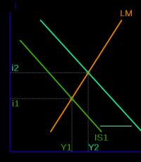
The described process of regulating the rotation speed when changing the fuel supply is presented in graphs (Fig. 4.24), which show the dependences of the engine and propeller power on the rotation speed at different fuel consumptions.
Developed engine power N doors has (with a certain error) a power-law dependence on the rotation speed: N dv ~ n (2…3) While the power consumption of the screw N in has a higher dependence on its speed: N in ~ n 5. The initial operating mode of the power plant is the intersection point of the engine power curve corresponding to fuel consumption Q T 0, with the power curve of a propeller whose blades are set at an angle φ 0 . This steady state of operation of the power plant corresponds to the rotation speed n 0 . With an increase in fuel supply, the engine power characteristic will be located above the initial one (shown by the dotted line Q T 1>Q T 0) due to the higher gas temperature in front of the turbine. As can be seen from the graph, the intersection of the propeller power curves at φ 0 and engine power at Q T 1>Q T 0 corresponds to a rotation speed that is greater n 0 . In this case, the centrifugal regulator, ensuring a constant rotation speed, will move the blades to a larger installation angle φ 1(dashed power curve, screw at φ 1>φ 0 ), which will cause a decrease in speed to previously set n 0.
Thus, with an increase in fuel supply, and, consequently, with an increase in engine power, the propeller will become heavier, i.e., the angle of installation of the blades increases and the thrust increases. When the fuel supply decreases, on the contrary, the regulator, maintaining a given rotation speed, moves the blades to smaller installation angles, thereby reducing engine thrust. Qualitative nature of the change in the angle of installation of the blades φ from the fuel supply Q T into the engine is shown in Fig. 4.25.
Speed characteristics of the propeller.
Let us now consider the operation of the propeller-regulator system when the flight speed changes and there is a constant supply of fuel to the engine. Let's assume that an airplane is switching from a climb mode to a level flight mode or from a level flight mode to a descent mode. In both cases, the flight speed will increase with a constant fuel supply.
In Fig. 4.26 shows graphs of changes in the available power of the gas turbine engine - N doors and power consumed by the propeller N in depending on flight speed V. In the region of subsonic flight speeds, the power (as well as thrust) of the engine N doors with increasing flight speed it decreases slightly at the same time N in falls more intensely. At speed V 0 The engine-propeller system operates in equilibrium mode ( N doors=N in). With an increase in flight speed to V 1 there is excess power ( N dv > N c), causing an increase in propeller speed. In an effort to maintain the speed at a given value, the centrifugal speed controller will move the blades to large installation angles φ 1 This will cause a decrease in speed due to the greater power consumption of the propeller N in (φ 1) and the equilibrium mode is restored, but at large blade angles.
Nature of change φ=f(V) shown in the graph in Fig. 4.27.
When the flight speed decreases, the control process proceeds in the reverse order. As the flight speed decreases, the angle of attack of the blades increases, and, consequently, the propeller becomes “heavier”. At the same time, the rotation speed decreases, and the regulator, trying to maintain the set value, moves the blades to smaller installation angles.
Altitude characteristics
The propeller-regulator system will also respond to changes in flight altitude, since the altitude characteristics of the engine and propeller change differently.
High-altitude characteristics of the theater N dv =f(h), presented on the graph in Fig. 4.28 (upper broken curve) has two characteristic breaks. On the ground, engine power is determined by the minimum fuel supply to the engine, which corresponds to the required takeoff power. In the altitude range (0…h 1) maintaining constant power (N door=const) by increasing the gas temperature in front of the turbine to the maximum permissible (increasing fuel supply) T g max. At altitudes from h 1 before h=11km engine power drops. In this altitude range, the decrease in atmospheric air density is partially compensated by an increase in the degree of air compression in the compressor, associated with a decrease in atmospheric temperature ( N dv ~ρ (0.8...0.9)).
At altitudes above 11 km, where the ambient temperature is constant, engine power decreases in proportion to the decrease in air density ρ .
The propeller power, as follows from Fig. 4.28 (a series of curves at different φ), decreases with increasing altitude in proportion to the change in air density ρ .
If we assume that the angle of installation of the propeller blades φ 0 on earth met the condition N doors=N in., then with increasing flight altitude N doors >N in. Such a discrepancy N doors And N in causes an increase in rotation speed, but the regulator, maintaining its set value, moves the propeller blades to large installation angles.
Thus, with an increase in flight altitude to h 1 there is an intensive increase in the installation angles of the blades; at the heights (h 1…11)km the angles continue to increase, but with less intensity; at altitudes above 11 km, the installation angle remains constant, since the change in engine and propeller power is equally proportional to the change in air density.
When the flight altitude decreases, the process of changing the installation angle will be reversed, i.e., the propeller blades will be moved to smaller installation angles. The nature of the blade angle change is shown in Fig. 4.29.
4.10. AEROMECHANICAL PROPELLERS
On airplanes with low-power engines, aeromechanical propellers are used, in which the blades turn automatically, without the use of extraneous energy sources and a speed controller. Thus, aeromechanical propellers are autonomous and automatic. Automatic rotation of the blades is achieved by changing the magnitude of the torques acting on the propeller blades in flight.
For conventional propellers, the magnitude of the moments of aerodynamic forces is small, and the direction of their action is determined by the magnitude of the angles of attack. If the blades are given a special shape or bent at an angle γ (Fig. 4.30) relative to the axis of rotation of the blade, then by changing the position of the center of pressure, the moments of aerodynamic forces will ensure rotation of the blade in the hub towards a decrease in the installation angle. Counterweights are installed on the blades of aeromechanical propellers, which create torques directed towards increasing the installation angle (tightening the propeller).
Counterweights are installed on the blades of aeromechanical propellers, which create torques directed towards increasing the angle of installation (tightening the propeller). Moments of the transverse components of the centrifugal forces of the blades Mts tend to rotate the blades in the direction of decreasing the angle of installation of the blade. Moments Mts, created by counterweights, are greater than the moments created by the transverse components of the centrifugal forces of the blades. In steady-state modes, the torque ratio must ensure the condition
M p = M c + M a.
However, the values of the above moments change depending on the flight mode, so choosing the correct ratio of torques acting on the propeller blades over a wide range of installation angles is a very important and difficult task. This ratio of moments should ensure that the propeller becomes “heavier” when the flight speed increases, and, conversely, when the flight speed decreases, the propeller should “lighten.” The rotation speed at a constant engine operating mode must remain constant.
In accordance with this, when the engine is operating in place, when the propeller thrust is maximum, and, therefore, the torque from aerodynamic forces is maximum, the propeller blades are set to the minimum angle stop. This ensures that the take-off (maximum) engine rotor speed is obtained and the most favorable conditions plane takeoff.
In flight, as the speed increases, the propeller thrust decreases, and the torques also decrease M a, and the moments of the centrifugal forces of the counterweights and blades, independent of the flight speed, retain the same values (at n=const). As a result, the torque ratio will change and the blades will gradually rotate towards increasing the installation angle, preventing the propeller from unwinding. Obviously, when the flight speed decreases, the picture will be the opposite. Thus, the blades of the aeromechanical propeller automatically change the installation angle depending on the flight speed. The rotational speed of the screw changes, but within relatively small limits.
The advantages of this type of propellers include: simplicity of design and operation, low weight and dimensions of the propeller hub, and the disadvantages are a decrease in the specified rotation speed as the aircraft ascends, which causes a decrease in engine power. With increasing altitude, due to a decrease in air density, the propeller thrust decreases. This causes the propeller to tighten and reduce engine speed and power. Vozn