Demountable contact connection cable lug. Installation of contact connections. Examples of dismountable connections of conductors with flat contact surfaces
Classification, requirements for design, reliability, safety and resistance to mechanical factors of contact electrical connections are given in GOST 10434-82. This standard applies to dismountable and permanent connections of buses, wires, cables, conductors made of copper, aluminum and its alloys, aluminum wires with leads of electrical devices, as well as contact connections of conductors with each other for currents of 2.5 A and above. In terms of the permissible electrical connection and the resistance of contact connections during through currents, the requirements of this standard apply to contact connections in the circuits of their grounding and protective steel conductors.
Permanent contact connections must be made by welding, soldering or pressing; dismountable, not requiring means of stabilizing electrical resistance - using steel fasteners protected from corrosion. Demountable contact connections that require means of stabilizing electrical resistance must be made using, either individually or in combination, the following means:
1) fasteners made of non-ferrous metals;
2) disc springs;
3) protective metal coatings of working surfaces selected in accordance with GOST 9303-84;
4) transition parts in the form of copper-aluminum plates in accordance with GOST 19357-81, copper-aluminum tips in accordance with GOST 9581-80 and hardware clamps made of alloyed aluminum in accordance with GOST 23065-78;
5) transition parts in the form of plates and tips made of hard aluminum alloy;
6) pin tips according to GOST 2358-79 made of hard aluminum alloy;
7) pin copper-aluminum tips according to GOST 23596-79.
Depending on the area of application, contact connections are divided into three classes. Contact connections of circuits whose cross-sections are selected based on long-term permissible current loads are classified as class 1. Contact connections of circuits whose conductor cross-sections are selected based on resistance to through currents, voltage loss and deviation, mechanical strength, and overload protection are usually classified as class 2. which also includes contact connections in circuits of grounding and protective conductors made of steel. Contact connections of circuits with electrical devices, the operation of which is associated with the release of a large amount of heat (heaters, resistors), are classified as class 3.
Collapsible contact connections are used with flat, pin, and socket terminals for both single-wire and multi-wire conductors of wires and cables. It is recommended that no more than two conductors be connected to each spade terminal bolt (screw) or pin. Screws and contact connections are recommended to be used with cylindrical or hexagonal heads.
1) Contact parts that have two or more holes for bolts in a transverse row are recommended to be made with longitudinal cuts;
2) The working surfaces of uncoated copper and aluminum-copper parts are cleaned immediately before assembly with linear fittings without damaging the copper shell of the latter; aluminum from aluminum alloys - cleaned and lubricated with Vaseline, neutral fairy tale CIATIM-221. Working surfaces with metal coatings are washed with organic solvents; the working surfaces of the contact parts when connecting by pressing, if they are made of copper, are cleaned, and if they are made of aluminum, they are cleaned and lubricated with quartz-vaseline (lead-vaseline) paste.
The electrical resistance of welded and soldered contacts must remain unchanged; for other contacts that have passed tests in accordance with GOST 17441-81, the resistance should not exceed the initial value by more than 1.5 times. When the rated current flows, the maximum permissible temperature contact connections of classes 1 and 2 should not exceed 95 °C (installations up to 1 kV), 90 °C (installations over 1 kV) for conductors without protective coatings on working surfaces; for conductors coated with base metals, 110 °C and 100 °C, respectively; for silver-plated conductors made of copper and its alloys, 125 °C and 120 °C, respectively.
Temperature of contact connections made of aluminum, aluminum and copper – 200 °C; from copper – 700 °C; made of steel – 400 °C. Contact connections must withstand vibration for an hour with a frequency of 40 - 50 Hz and an amplitude of 1 mm. It is recommended to tighten the bolts with torque wrenches (DK-25), and the screws with thoriated screwdrivers, the torques for them are in accordance with GOST 10434-82.
To make contact connections of current-carrying parts of electrical installations, various technological methods are used: electric welding with contact heating and a carbon electrode, gas-electric, gas, thermite, contact butt welding, cold pressure welding, soldering, pressing, twisting, tightening (bolts, screws), etc.
Electric welding of conductors contact heating used for terminating, connecting and branching aluminum wires with a cross-section of up to 1000 mm 2, as well as for connecting aluminum conductors with copper ones. Contact heating welding using filler materials is used for connecting and terminating aluminum stranded wires and cables with a cross-section of up to 2000 mm 2, electric welding carbon electrode– for connecting aluminum busbars of various sections and configurations, gas-electric welding - mainly for connecting aluminum and copper conductors. The advantage of the latter is that it is performed without fluxes, but it requires the use of relatively bulky equipment and the use of expensive gas. Therefore, gas-electric welding is used for contact connection of busbars made of aluminum alloys of type AD31 and copper busbars. Gas welding is intended for connecting copper and aluminum wires of various sections and configurations; its implementation requires bulky equipment and compliance with special safety regulations when working with gases.
Termite welding can be used to connect steel, copper and aluminum wires and busbars of almost all sections; however, its most appropriate use is for contact connections of bare wires of power lines in the field. For thermite welding, simple equipment is used; it does not require electricity consumption; it is also necessary to create special conditions for storing thermite cartridges and matches. Thermite-crucible welding is used to connect steel strips of grounding loops and lightning protection cables.
Contact butt welding is used when connecting aluminum busbars to copper ones (copper-aluminum adapter plates and copper-aluminum lugs).
Cold pressure welding is used to connect aluminum and copper busbars of medium sections and single-wire wires with a cross-section of up to 10 mm 2; it does not require additional materials or contact fittings.
Soldering make connections of both aluminum and copper wires of any cross-section; This method does not require complex equipment, but is labor-intensive.
Crimping designed for contact connections of aluminum, steel-aluminum and copper insulated and non-insulated wires with a cross section of up to 1000 mm 2. Crimping connections do not create thermal effects on the insulation, but when terminating and connecting conductors, it is necessary to select tips, sleeves, as well as tools (punches and dies) especially carefully. This method is used both in cable and overhead lines.
Twisting wires are used on communication lines, and with the help of connectors they connect the wires of overhead power lines (OHT).
The use of one or another contact connection method depends on the materials of the conductors being connected, their cross-section and shape, the voltage of the electrical installation, installation conditions (availability of mechanisms, devices, materials, electricity, etc.), as well as operating requirements.
Wires of overhead lines up to 1 kV are connected in spans by twisting in oval tubes; Single-wire wires may be connected by twisting followed by soldering or lap welding (connecting single-wire wires by butt welding is not allowed). Wires in the loops of anchor supports are connected using anchor and branch wedge clamps, twisting in oval tubes, die or hardware press clamps, and welding.
Branches of overhead line wires must be made with pressed or die clamps.
Connection methods for BJI wires above 1 kV depend on their cross-section. In spans, aluminum wires with a cross-section of up to 95 mm 2 , steel-aluminum wires with a cross-section of up to 185 mm 2 and steel with a cross-section of up to 50 mm 2 are connected by twisting using oval joints; aluminum wires with a cross-section of 120 - 185 mm2 and steel wires with a cross-section of 70 - 95 mm2 - crimping using oval connectors with additional thermite welding of the ends; aluminum and steel-aluminum wires with a cross-section of 240 mm 2 and more - using connecting pressed clamps. In the loops of anchor and corner supports, steel-aluminum wires with a cross-section of up to 240 mm 2 and aluminum wires with a cross-section of up to 95 mm 2 are connected by thermite welding; steel-aluminum wires with a cross-section of 300 mm 2 and above - with pressed connection clamps; wires of different brands - with hardware pressed clamps.
The use of the contact connection method depends on the materials of the conductors being connected, the cross-section, shape and voltage of the electrical installation, and installation conditions. Overhead lines (wires) up to 1 kV in spans are connected by twisting in oval tubes; single-wire wires can be connected by twisting followed by soldering or lap welding (butt welding of single-wire wires is not allowed). In the loops of anchor supports, the wires are connected using anchor and branch wedge clamps, twisting in oval tubes, die or hardware press clamps and welding.
The preparation of conductors for a contact connection is carried out depending on the method of making the connection. In order to ensure metallic contact between the connected conductors, their contact surfaces are first cleaned of all kinds of films, using washing, chemical dissolution of films and mechanical cleaning; often these methods are used together. Mechanical cleaning in combination with rinsing or dissolving is effective. Methods for cleaning surfaces are selected depending on the materials of the contact elements, the presence of protective metal coatings on them, the type of films and the method of making the contact connection.
Correct and high-quality execution of operations for connecting, branching and terminating cores of wires and cables determines the reliability of operation of internal and external electrical wiring. These wiring elements must have the necessary mechanical strength and low electrical resistance, maintaining these properties for the entire period of operation.
Wires and cables with aluminum and copper conductors are used for electrical wiring. For economic reasons, electrical wiring is usually carried out using wires and cables with aluminum conductors. However, aluminum has properties that contribute little to the reliability of the connection. One of them is increased (compared to copper) fluidity and oxidation with the formation of non-conducting films. Aluminum oxide creates high contact resistance, leading to poor electrical contact and excessive heating. The oxide film creates difficulties when soldering and welding wires, since it has a melting point of 2050 °C, while the melting point of aluminum itself is only 660 °C.
During operation, screw and bolt clamps of connections of aluminum and copper wires require monitoring and periodic tightening.
The design of the clamp for connecting aluminum conductors must provide the following properties:
Constant pressure on the wires when their fluidity appears;
A device that protects wires from spreading out from under the contact screw;
Galvanic coating of parts.
These requirements are met by a clamp specially designed for connecting aluminum conductors (Fig. 2.1). The spring washer of the clamp ensures constant pressure on the connected wires, and the stop prevents the wire from being squeezed out from under the contact clamp. In some designs, the spring washer and the stop that limits spreading are made in the form of a single star washer. It is necessary to assemble the clamp with all parts, since the absence of any of them will certainly lead to poor contact.
Rice. 2.1. Clamp for connecting aluminum wires
1 – screw; 2 – spring washer; 3 – washer or contact clamp base; 4 – current-carrying core; 5 – stop that limits the spreading of the aluminum conductor.
In some types of connections, a stranded copper current-carrying core with a cross-section of 1.0 - 2.5 mm2 is terminated in the form of a rod with a half-filled solder POS-40.
The contact terminals of plug sockets up to 10 A and switches from 4 A and above allow the connection of copper and aluminum wires with a cross-section from 1 to 2.5 mm 2, and for 1 A switches - only copper wires with a cross-section from 0.5 to 1 mm 2. The connection of aluminum wires in the clamp must be terminated in the form of a ring, copper wires - in the form of a ring and a rod (Fig. 2.2). Before putting into contact, the aluminum wire ring is cleaned and lubricated with quartz vaseline or zinc vaseline paste. In plug sockets up to 10 A, no more than two copper or aluminum wires with a cross-section of up to 4 mm 2 can be connected to one contact.
Rice. 2.2. Termination of wires
The method of connecting and terminating aluminum and copper wires and cables by crimping has become widespread, which provides reliable electrical contact and the necessary mechanical strength, and is also simple to perform. Crimping is performed using hand pliers, mechanical and hydraulic presses using replaceable dies and punches. Sleeves are used to connect the cores of wires and cables (Fig. 2.3), and lugs are used for termination.
Soldering and welding are used to connect and branch wires in cases where all others cannot be used - crimping, screw clamps and welding. Soldering creates good electrical contact, but this connection is fragile, so the wires must be twisted before soldering. The connection and branching of copper conductors with a cross-section of up to 6 mm 2 is carried out by soldered twisting. Twisting followed by soldering is a method of connecting and branching single-wire copper and multi-wire wires of brands PR, PV, PRVD, PRD with a cross-section of 1.5 - 6 mm 2 in open electrical wiring on rollers and insulators (Fig. 2.4.) This method of connection and branching is also used in electrical wiring made with flat wires PPV and others, when branch boxes do not have liners with contact clamps, as well as in some other cases.
Fig.2.3. Crimping of aluminum wires with GAO sleeves:
a – one-sided; b – double-sided crimping
The method of connecting wires by twisting is simple in execution, but it requires subsequent soldering of the connection, since even a well-made twist has a transient contact resistance that is several times higher than with other connection methods - crimping, soldering, welding, bolted or screw connections. When twisted, the wires have few contact points, and when current flows through the connection, the contact can overheat, which sometimes causes a fire. For this reason, twisted connections without soldering are not allowed.
When soldering single-wire aluminum conductors with a cross-section of 2.5 - 10 mm2, the connection and branch are made in the form of a double twist with a groove. The insulation is removed from the conductors, cleaned to a metallic shine with sandpaper or cord tape, and overlapped with a double twist to form a groove where the conductors touch (Fig. 2.5).
Rice. 2.4. Connection and branching of copper wires of PV, PR, PRD, PRVD brands
Rice. 2.5. Connection of single-wire aluminum wires with double twisting and groove
Welding is used for terminating and connecting current-carrying conductors of wires and cables of all sections and for aluminum conductors with copper conductors with a conductor cross-section of no more than 10 mm 2. This joining method requires the use of special fluxes, welding machines and other special equipment.
Concern "Electromontazh"
Installation instructions for bus contact connections
between each other and with the terminals of electrical devices
UDC 621.315.68 (083.96)
Instead of VSN 164-82
This instruction has been developed to develop the basic provisions of GOST 10434-82, GOST 17441-84, the current Electrical Installation Rules (PUE) and building codes and regulations (SNiP).
The instructions apply to dismountable and non-separable contact connections1 of busbars up to 152 mm thick, flexible busbars and profiles3 (channel, trough, “double T”, etc.) made of aluminum, solid aluminum alloy AD31T4, copper and steel, as well as connections of busbars with terminals electrical devices.
_________________
- An explanation of the terms found in the instructions is given in Appendix 1
- Technical requirements for contact connections also apply to busbars with a thickness of more than 15 mm
- Hereinafter referred to as the tire
- Hereinafter referred to as aluminum alloy
- Hereinafter referred to as output
The instructions are intended for design, installation and operating organizations.
1. GENERAL REQUIREMENTS
1.1. The interconnection of busbars made of homogeneous metals, branches from these busbars and connections of aluminum busbars and aluminum alloy busbars with terminals made of aluminum and aluminum alloys are made collapsible or non-dismountable. Connections of busbars made of dissimilar materials and in cases where operating conditions require periodic disassembly of the connections should, as a rule, be made collapsible.
1.2. Contact connections depending on technical requirements requirements for them according to GOST 10434-82*, are divided into classes 1, 2 and 3.
The class of contact connections depending on their area of application is given in table. 1.1.
Table 1.1.
| Application area | Recommended contact class |
| 1. Contact connections of circuits whose conductor cross-sections are selected according to permissible long-term current loads (power electrical circuits, power lines, etc.) | 1 |
| 2. Contact connections of circuits, the conductor cross-sections of which are selected for resistance to through currents, voltage loss and deviation, mechanical strength, and overload protection. Contact connections in circuits of grounding and protective conductors made of steel | 2 |
| 3. Contact connections of circuits with electrical devices, the operation of which is associated with the release of a large amount of heat (heating elements, resistors) | 3 |
Linear contact connections of power circuits must be of class 1.
1.3. Depending on the climatic version and the category of placement of electrical devices in accordance with GOST 15150-69*, contact connections in accordance with GOST 10434-82* are divided into groups A and B.
Group A includes contact connections of electrical devices of all designs located in rooms with air-conditioned or partially conditioned air (placement category 4.1), and electrical devices of designs U, HL and TS, located in enclosed spaces (metal with thermal insulation, stone, concrete, wood ) with natural ventilation without artificially controlled climatic conditions (location category 3), and in rooms with artificially controlled climatic conditions (location category 4) in an atmosphere of types I and II according to GOST 15150-69*.
Group B includes contact connections of electrical devices of other designs and placement categories in atmospheres of types I and II and electrical devices of all designs and placement categories in atmosphere types III and IV.
1.4. Contact connections must be made in accordance with the requirements of GOST 10434-82*, GOST 17441-84, standards, technical specifications for specific types of electrical devices, SNiP 3.05.06-85, these instructions for working drawings approved in the prescribed manner.
1.5. Requirements for permanent connections
1.5.1. The surface of the seams of welded joints should be uniformly scaly without sagging. The seams should not have cracks, burns, lack of fusion longer than 10% of the seam length (but not more than 30 mm), unfused craters and undercuts with a depth of 0.1 of the tire thickness (but not more than 3 mm). Welded joints of expansion joints should not have undercuts or lack of penetration on the tapes of the main package.
1.5.2. Connections made by crimping should not have cracks in the tip shank, sleeve, or clamps at the crimping site; the holes must be located symmetrically and coaxially, the geometric dimensions of the pressed part of the connection must comply with the requirements of standards, specifications, and technological documents.
1.5.3. Welded and pressed connections that do not work in tension must withstand stresses arising from the influence of static axial loads of at least 30% of the temporary tensile strength of the entire flexible tire; tensile - at least 90% of the tensile strength of the entire flexible tire.
1.5.4. The ratio of the initial (after welding) resistance of the contact connections to the resistance of the control section of the bus with a length equal to the length of the contact connection should be: for class 1 - no more than 1 (unless otherwise specified in the standards and specifications for specific types of electrical devices); for class 2 - no more than 2; for class 3 - no more than 6.
In contact connections of buses of different conductivity, comparison should be made with a bus of lower conductivity.
1.5.5. The electrical resistance of welded joints that have passed the tests must remain unchanged; for connections made by crimping, electrical resistance after testing it should not exceed the initial value by more than 1.5 times.
1.5.6. When the rated current flows, the heating temperature of permanent contact connections (classes 1 and 2) should not exceed the values indicated in table. 1.2. The heating temperature of class 3 contact connections is established by standards and specifications for specific types of electrical devices.
1.5.7. The temperature of permanent contact connections when testing for resistance to through currents should be no more than 200°C for connections of busbars made of aluminum and its alloys, as well as for connections of these busbars with copper, and 300°C for connections of copper busbars. After testing for resistance to through currents, contact permanent connections should not have mechanical damage that would prevent their further operation.
1.5.8. Contact connections, in accordance with their design and placement category according to GOST 15150-69*, must withstand the effects of climatic factors external environment specified in this standard, as well as GOST 15543.1-89 E, GOST 16350-80, GOST 17412-72* or in standards and specifications for specific types of electrical devices.
Table 1.2
Heating temperature of contact connections
1.6. Requirements for dismountable connections
1.6.1. Collapsible tensile contact connections must withstand stresses arising from static axial loads of at least 90% of the tensile strength of the entire flexible busbar.
1.6.2. The ratio of the initial (after assembly) resistance of dismountable contact connections (except for connections with pin terminals) to the resistance of the control section of the bus with a length equal to the length of the contact connection must comply with the requirements of clause 1.5.4.
1.6.3. The initial resistance of class 1 contact connections with pin terminals should not exceed the values indicated in the table. 1.3. The resistance of contact connections of classes 2 and 3 is indicated in standards and specifications for specific types of electrical devices.
1.6.4. The electrical resistance of collapsible contact connections that have passed the tests should not exceed the initial resistance by more than 1.5 times.
Table 1.3.
Initial resistance of contact connections of busbars with pin terminals
1.6.5. When the rated current flows, the heating temperature of dismountable contact connections of classes 1 and 2 should not exceed the values indicated in table. 1.2. The heating temperature of class 3 contact connections is established in standards and specifications for specific types of electrical devices.
1.6.6. The temperature of dismountable contact connections and mechanical strength when testing for resistance to through currents must comply with the requirements of clause 1.5.7.
1.6.7. In collapsible contact connections, fasteners with a strength not lower than that indicated in the table should be used. 1.4.
Table 1.4.
Class and strength group of fasteners
Fasteners must have a protective metal coating in accordance with GOST 9303-84. For contact connections of group A, the use of blued steel bolts, nuts, and washers is allowed.
1.6.8. Collapsible contact connections of busbars with leads, as well as collapsible linear contact connections exposed to through currents short circuit, vibrations, as well as those located in explosive and fire hazardous areas, must be protected from self-unscrewing by locknuts, spring washers, disc springs or other methods. Spring washers should be used in connections with bolts up to M 8 inclusive.
1.6.9. Demountable contact connections must withstand the effects of environmental climatic factors in accordance with clause 1.5.8.
2. PERMANENT CONTACT CONNECTIONS
Structural elements and dimensions of welded contact connections of busbars should be selected in accordance with the recommendations of GOST 23792-79.
The main types of welded joints on busbars are: butt, corner, lap, T and end joints (Table 2.1).
Determination of types of welded joints - according to GOST 2601-84.
Methods for welding tires from various materials are indicated in table. 2.2.
When choosing a welding method, keep in mind:
1) For carbon electrode welding, no special welding equipment is required, while for welding in a shielding gas (argon) environment, it is necessary to purchase a special semi-automatic welding machine, or an installation for manual argon-arc welding.
2) Due to its characteristics, welding with a carbon electrode is possible only in the lower position; welding in argon (both manual and semi-automatic) can be performed in all spatial positions.
3) Manual argon-arc welding with a tungsten electrode is effective for tire thicknesses up to 6 mm. At large thicknesses, the productivity of this method decreases sharply, especially at low air temperatures, which leads to a sharp increase in energy costs for welding.
Table 2.1.
Main types of welded joints and tires
1 - tire; 2 - weld; 3 - package of flexible tapes; 4 - wire core (flexible bus).
4) Welding in argon (manual and semi-automatic) provides more high quality welded joints compared to carbon electrode welding.
5) When welding with a carbon electrode, the main factors that have a harmful effect on the welder’s body and the environment are ultraviolet radiation and the release of large amounts of welding aerosol and dust consisting of metal vapor, its oxides and flux combustion products. These emissions must be removed directly from the welding site and filtered before being released into the environment.
6) When welding in argon, the basis of harmful emissions is ozone, which also must be removed from the welding site.
Table 2.2.
Tire welding methods
_______________
1 Welding AD31 alloy with a carbon electrode is not recommended.
2.1. Welding of aluminum tires
Manual argon-arc welding with a tungsten electrode
2.1.1. For manual argon-arc welding with a tungsten electrode, stationary installations such as UDGU-301 and UDG-501-1, commercially produced by industry, are intended.
For this purpose, it is allowed to use a welding arc power source manufactured by the Rostov experimental plant NPO Montazhavtomatika, as well as a combined welding transformer of the TDK-315 type, manufactured by the Kharkov enterprise Prommontazhelektronika. The source must be equipped with a manual welding torch developed by LenPEI of the Elektromontazh concern (industrial torches require water cooling).
2.1.2. In the absence of the specified settings, the welding station should be assembled according to the diagram shown in Fig. 2.1., from the equipment specified in table. 2.3.

Rice. 2.1. Diagram of a post for manual argon-arc welding on “alternating current”
TS - welding transformer; OS - oscillator; RB - ballast rheostat; G - welding torch; R - gearbox; B - cylinder.
When choosing equipment, it should be borne in mind that for normal operation of UDG installations and EZR welding torches, cooling water is required.
Table 2.3.
Equipment for manual argon-arc welding of aluminum
| Name of equipment | Type, brand1 | GOST, TU | Purpose |
| 1. Welding transformer | TD-306 TDM-503 |
TU 16-517-973-77 TU 16-739-254-80 |
Welding power source |
| 2. Gas-electric burners | EZR | TU26-05-57-67 | Supplying welding current to the electrode; shielding gas supply |
| LenPEI designs | LE 12550 | ||
| 3. Arc exciter-stabilizer or welding oscillator | VSD-01 | TU 16-739.223-80 | Excitation and stabilization of arc combustion |
| OSPZ-2M | TU 1-612-68 | ||
| OSM-2 | |||
| 4. Ballast rheostat | RB-302 | Regulation of welding current, suppression of the DC component in the welding circuit | |
| 5. Balloon reducer | AR-40 | TU26-05-196-74 | Reducing argon pressure to operating value |
| DKP-1-65 | TU26-05-463-76 | ||
| 6. Balloon | 40-150 | GOST 949-73 | Transportation and storage of argon |
______________________
1 Use any of the specified types
2.1.3. The list of materials required to perform manual argon-arc welding with a tungsten electrode is given in table. 2.4.
Table 2.4.
Materials for manual argon-arc welding of aluminum
______________
1 It is allowed to manufacture arc furnace electrodes or electrolyzer blocks from waste graphite electrodes
2.1.4. Preparation of tires for welding, in addition to straightening and cutting to size, should include:
- processing of welded edges depending on the thickness of the material to ensure the required groove dimensions in accordance with GOST 23792-79;
- drying the edges to be welded if they are covered with moisture;
- cleaning the edges to be welded after assembly with a steel wire brush and degreasing them with a solvent: gasoline or acetone;
- heating, if necessary, the edges to be welded to 200-250°C, if welding is performed at a temperature environment below 0°C.
For drying, as well as for heating the edges of tires and profiles, gas burners or flexible electric heaters (GEN), manufactured according to TU36-1837-75, can be used.
2.1.5. Welding wire preparation should include:
- degreasing and cleaning (mechanical or chemical) of the surface (see Appendix 2);
- cutting into bars of the required length.
2.1.6. When performing welding, the following technological recommendations must be observed:
- position the tungsten electrode from the burner nozzle no more than 5 mm;
- starting welding, excite the arc on the graphite plate, heat the tungsten electrode and then transfer the arc to the edges of the tires without touching them with the electrode;
- When welding, try not to touch the metal of the product with the tungsten electrode, as this leads to disruption of the stability of the welding process, contamination of the seam and rapid consumption of the electrode;
- maintain an arc no longer than 10 mm;
- When finishing welding, after the arc breaks, do not move the torch away from the end of the seam for several seconds, protecting the cooling metal with a jet of argon;
- when welding outdoors, protect the welding site from wind and precipitation with screens, awnings, etc., and also, if necessary, increase the argon flow rate enough to ensure effective protection of the molten metal.
2.1.7. At the beginning of welding, it is necessary to warm up the welded edges of the tires by moving the welding arc along them, then concentrate the arc at the beginning of the seam, melt the edges until a weld pool is formed, insert a filler rod into it and begin to move the arc evenly along the joint at the speed of melting of the edges. The welding diagram is shown in Fig. 2.2.
Modes and approximate consumption of materials during welding are given in table. 2.5.

Rice. 2.2. Manual argon-arc welding with a tungsten electrode
a) welding diagram; b) diagram of the movement of the electrode during welding;
1 - weld; 2 - burner; 3 - electrode; 4 - filler rod.
Table 2.5.
Modes of manual argon-arc welding of aluminum
| Tire thickness, mm | Welding* current, A | Electrode diameter, mm | Consumption per 100 mm seam | ||
| argon, l | additives, g | ||||
| 3 | 130-150 | 3 | 3 | 9 | 5,6 |
| 4 | 150-170 | 3 | 3 | 10 | 6 |
| 5 | 170-180 | 3 | 3 | 10 | 6,8 |
| 6 | 190-200 | 4 | 4 | 11,5 | 8,5 |
| 8 | 220-225 | 5 | 5 | 12 | 11-20 |
| 10 | 240-250 | 5 | 6 | 14 | 35 |
| 12 | 290-300 | 6 | 8 | 16 | 45 |
__________
* Variable.
2.1.8. When welding in vertical, horizontal and overhead positions, to prevent swelling of the metal and better formation of the seam, you should:
- reduce the welding current (by 10-20%);
- increase the argon consumption against the values indicated in the table. 2.5 to ensure effective seam protection;
- Welding should be performed with small cross-section beads and a short arc;
- when welding in vertical and horizontal positions, place the welding torch below the weld pool.
Semi-automatic argon-arc welding with consumable electrode
2.1.9. For semi-automatic welding of aluminum in argon, semi-automatic machines such as PDI-304 and PDI-401, produced by industry, are intended, as well as semi-automatic machine PRM-4, produced by the pilot plant of the Institute of Assembly Technology (NIKIMT)1, but supplied without a welding current source. As such, welding rectifiers VDU-505, VDU-506, VDG-303, etc. are used. To regulate the flow of argon during welding, a balloon reducer is used, see table. 2.3.
________________
1 Semi-automatic machine PRM-4, manufactured by NIKIMT, is included in the set of the product “Backpack assembly semi-automatic machine PRM-4 with attachment PV 400”, supplied by the Moscow Experimental Plant of Electrical Installation Equipment (MOZET).
- replace the steel spiral in the torch hose, which is the guide channel for the steel welding wire, with a tube made of fluoroplastic, Teflon or polyamide, i.e. made of materials that provide minimal friction when passing aluminum wire;
- perform mechanical processing of the burner parts, inside which the welding wire passes, in such a way as to eliminate sharp edges at the joints of the parts and sharp bends in the path;
- manufacture fluoroplastic bushings for inserting aluminum wire into the feed mechanism and into the torch hose, eliminating delays in wire feeding;
- replace (if necessary) the knurled feed rollers with smooth rollers.
2.1.11. The materials required for semi-automatic argon-arc welding are given in table. 2.4, however, instead of tungsten electrodes, it is necessary to use copper-graphite tips of the KTP-DGr9 grade according to TU 16-538.39-83, used in welding torches as an element that transmits welding current to the electrode wire.
Preparation of tires for welding - in accordance with clause 2.1.4.
2.1.12. Before use, the welding wire should be chemically cleaned (see Appendix 2) and, depending on the design of the semi-automatic machine, wound evenly, layer by layer, onto a reel or placed directly in a coil on the turntable of the feed mechanism.
2.1.13. During welding, the seams to be joined must be firmly secured with clamps or short (@30 mm) welds - tacks.
2.1.14. When welding, the torch should be driven at a uniform speed at an angle forward so that the argon stream is directed forward, ensuring reliable protection of the weld pool from air.
If it is necessary to obtain a larger seam width, it is also necessary to perform transverse vibrations with the torch. The welding diagram is shown in Fig. 2.3. The main welding modes are given in table. 2.6.
Table 2.6.
Modes of semi-automatic argon-arc welding of aluminum

Figure 2.3. Scheme for performing semi-automatic welding in various spatial positions
a) bottom; b) vertical; c) ceiling
1 - welding torch; 2 - weld.
2.1.15 When welding multilayer seams, if a dark coating appears on the surface of the seam, the latter should be removed with a rag moistened with gasoline or cleaned with a wire brush. Only after this can subsequent layers of sutures be applied.
2.1.16. When welding in vertical, horizontal and overhead positions, to prevent the molten metal from flowing down, it is necessary:
- reduce the welding current (by 10-20%);
- weld with a short arc, applying beads of small cross-section;
- when the metal overheats, which is visually expressed in its melting, take short breaks in work (to cool the metal).
2.1.17. Welding should be performed with an open arc using direct current of straight polarity (minus the power source - on a carbon electrode). To protect the weld metal from oxidation, it is necessary to use fluxes. The method is characterized by a large volume of molten metal, so welding should be performed only in the lower position of the seam with careful shaping of the joint to prevent the flow of molten metal.
After welding, flux residues must be removed.
2.1.18. For manual arc welding with a carbon electrode, you should assemble a welding station according to the diagram in Fig. 2.4. from the equipment specified in table. 2.7.
Table 2.7
Equipment for manual welding of aluminum with carbon electrode
_________________
1 Use any of the specified types.
2.1.19. The materials required for welding are listed in table. 2.8.

Rice. 2.4. Diagram of a post for manual welding with a carbon electrode on direct current
IP - welding current source; E - carbon electrode; Ш - weldable tires.
Table 2.8.
Materials for manual welding of aluminum with carbon electrode
- It is allowed to produce rods by cutting from sheets or tires or by casting from tire metal.
- It is allowed to manufacture electric arc furnaces from electrodes (waste) (Appendix 4).
- It is allowed to manufacture graphite anodes, cathode blocks, and arc furnace electrodes from waste.
2.1.20. Preparing tires for welding involves cutting the edges to be welded at right angles. In this case, the edges are not beveled, but it is necessary to use devices with forming graphite pads that prevent the flow of molten metal.
2.1.21. Filler rods should be cleaned and degreased before welding.
Before welding, it is necessary to apply VAMI flux, diluted with water to a creamy mass, to the edges of the tires and to the filler rods, or pour it onto the edges in powder form.
2.1.22. At the beginning of welding, the welded edges should be heated by moving the extended welding arc along them, then concentrate the arc at the beginning of the seam, melt the edges of the tires until a weld pool is formed and begin moving the arc along the joined edges at the speed of their melting. It is necessary to insert a filler rod into the rear edge of the weld pool, which is used to smoothly and evenly mix the weld pool to remove oxides and slags.
2.1.23. When finishing the seam, you should allow the metal to harden, and if a shrinkage hole forms, excite the arc again and melt the crater.
2.1.24. At the end of welding, the seams must be thoroughly cleaned of slag, flux residues, and frozen drops of metal.
The welding diagram is shown in Fig. 2.5.

Rice. 2.5. Carbon electrode welding diagram
1 - tire; 2 - graphite lining; 3 - graphite block for shaping the end of the seam; 4 - filler rod; 5 - carbon electrode; 6 - weld pool; 7 - seam.
Table 2.9.
Modes for manual welding of aluminum with a carbon electrode
| Tire thickness, mm | Gap between tire edges, mm | Welding current1, A | Diameter of filler rod2, mm | Consumption per 100 mm seam, g | |
| additives | gumboil YOU | ||||
| 3 | - | 150 | 5 | 9 | 1-2 |
| 4 | - | 200 | 5 | 10 | 2-3 |
| 5 | - | 200 | 5 | 18 | 3-5 |
| 6 | - | 250 | 8 | 25 | 4-6 |
| 8 | - | 300 | 10 | 35 | 5-8 |
| 10 | - | 350 | 12 | 46 | 7-10 |
| 12 | - | 400 | 12 | 57 | 9-12 |
| 15 | - | 450 | 15 | 80 | 11-13 |
- The current is constant, the polarity is straight.
- Rods cut from tires or sheets must have a square cross-section with a side of the square equal to the diameter of the round rod indicated in the table.
Features of welding technology for aluminum conductors of various profiles
Rectangular tires
The main types of welded joints of rectangular busbars are presented in Fig. 2.6.
2.1.25. When welding in the installation area, portable assembly devices should be used to form seams, attached directly to the tires being welded (Fig. 2.7.).
2.1.26. When laying busbars individually, as a rule, butt connections should be made, and when installing busbar packages, overlap, end and corner connections should be made.

Rice. 2.6. Basic welded joints of rectangular busbars
a) butt joints of busbars; b) connections at an angle; c) welding the branch to the busbar; d) welding the branch to the busbar with an overlap; e) welding the compensator to the tires; c) T-joint of tires; g, h) welding of tires along the upper edges
1 - tire; 2 - weld; 3 - package of flexible tapes.

Rice. 2.7. Portable devices for welding tires during installation
a) for butt welding; b) for welding branches
1 - tire; 2 - clamp; 3 - graphite block; 4 - base of the device; 5 - folding clamp; 6 - branch.
2.1.27. Lap and end connections should be used for welding branches to single-lane and multi-lane busbars. In this case, the branches can also be multi-lane and have both smaller and equal thickness. Welding modes should be set for a tire of smaller thickness.
When welding, it is necessary to use special devices that prevent the leakage of aluminum and ensure the possibility of obtaining a weld of the required size (Fig. 2.8, 2.9).

Rice. 2.8. Welding tires along the upper edges with a semi-automatic machine in argon
1 - tires; 2 - clamp; 3 - semi-automatic burner; 4 - welding seam.

Rice. 2.9. Welding tire packages along the upper edges (carbon electrode)
1 - tires; 2 - assembly device; 3 - carbon forming inserts; 4 - additive; 5 - electrode.
2.1.28. When installing complete busbars (such as ShMA, for example), the main volume of work associated with the manufacture of enlarged sections should be carried out in the workshop of electrical installation workpieces, where the overlapping busbars of sections of standard length should be connected by welding along the upper and lower edges with edging of the assembled unit (see table 2.1, end connection) to increase its strength during transportation and installation. Busbar connections assembled at the design level should be welded only on one side accessible for welding.
Profiles and pipes
2.1.29. For the manufacture of current conductors for various special purposes, in addition to rectangular busbars, extruded aluminum profiles and pipes in accordance with GOST 15176-89 E of the following types should be used: channel, I-beam, oblique angle, round pipe, etc.
Examples of welded connections of tires from profiles and pipes are shown in Fig. 2.10 and 2.11.
2.1.30. Box-shaped busbars should be made by welding two channels, assembled with shelves inward, using clamps and gap clamps - pieces of aluminum plates (Fig. 2.12); the length of the welds is approximately 100 mm, the distance between the seams (step) is 1-2 m; seams must be made on both sides using semi-automatic argon-arc welding.
2.1.31. Technological process The production of current conductors from profiles and pipes must be built on the principle of welding profile sections into a continuous thread, from which sections of the required length are cut off for the assembly of three-phase sections of the current conductor. The length of the conductor sections should be determined by the conditions of transportation and installation, and, as a rule, should be chosen as a multiple of the distance between supports or temperature compensators.
2.1.32. Areas for manufacturing conductors should be equipped with roller stands to facilitate the movement and alignment of profiles; mechanical rotators (tilters), ensuring welding is performed in a position convenient for work (Appendix 6): rotary saws, allowing cutting of a profile at a given angle, and other necessary mechanisms.

Rice. 2.10. Welded connections of conductors made of aluminum channels and I-beams
a, k) conductor sections with a welded liner; b, m) butt joints; c, d, o) T-joints; d, p) corner connections; f, g, h, p, s, t) branches with flat busbars; i, m) compensators; j) ending the profile with flat tires.
1 - channel; 2 - liner; 3 - seam; 4 - flat tire; 5 - compensator; 6 - flanged I-beam.

Rice. 2.11. Welded joints of tires from pipes
a) butt; b) angular; c) T-bar; d, e, f) with rectangular tires; g) a tip made by flattening the end of the pipe; h) tip with a welded copper-aluminum plate; i) a compensator made of wires, welded directly to the pipe; j) compensator made of wires welded to the flanges.
1 - pipe; 2 - weld; 3 - flat tire; 4 - copper-aluminum plate; 5 - wire compensator; 6 - flange.

Rice. 2.12. Welding a box bus from an aluminum channel
1 - channel; 2 - compression; 3 - semi-automatic welding torch; 4-connecting weld.
2.1.33. To facilitate the assembly, alignment and welding of busbars of abutting sections of current conductors, liners or backing rings made from aluminum strip 3-5 mm thick and 50-80 mm wide should be used. The insert (ring) should be attached with tacks to one of the ends of the profile and, during subsequent welding of the joined profiles, serve as a forming lining, preventing burns and leakage of molten metal.
2.1.34. When welding a “flanged I-beam” profile, the weld should be applied only along the outer perimeter of the profile. The joint between the inner walls of the profile may not be welded.
2.1.35. In channel and I-beam conductors, to compensate for temperature changes in length, as a rule, busbar compensators K52-K56 according to TU36-14-82 should be used. The designs of welded joints of expansion joints with profiles are shown in Fig. 2.10.
The cross-section of the compensator must be equal to the cross-section of the profile. Since the thickness of the compensator, welded only to two flanges of the profile, is greater than the thickness of its flanges, aluminum plates of the appropriate thickness should be pre-welded to them from the outside (Fig. 2.13).

Rice. 2.13. Welding expansion joints to the conductor
1 - conductor sections; 2 - compensators; 3 - strips; 4 - weld.
When welding T-joints of pipes, the end of the adjacent (branch) pipe must be processed so that it mates with the surface of the main pipe, or a hole should be drilled in the main pipe equal to the outer diameter of the branch pipe. The assembled assembly must be welded around the perimeter of the pipe interface. Welding modes must correspond to the welding modes of pipes with thinner wall thickness.
When welding branches, special devices should be used to fix the position of the pipes during welding (Fig. 2.14), or assembly should be done using tack welding tools. In this case, it is enough to press the rectangular tires with a clamp while welding (Fig. 2.15).
2.1.36. Compensators for tubular conductors must be made, as a rule, from bare aluminum wire grade A in accordance with GOST 839-80* E. To do this, depending on the diameter of the pipe, pieces of wires 300-600 mm long should be cut.
Structurally, expansion joints should be made by fusing the ends of the wires into a ring monolith (Fig. 2.11 i) or by welding the wires to the flanges (Fig. 2.11k) with rivet seams.

Rice. 2.14. Device for assembling pipe T-joints for welding
1 - rocker arm; 2 - folding bar; 3 - bracket; 4 - folding screw; 5 - heel; 6 - clamping screw.

Rice. 2.15. Assembly of a rectangular tire with a pipe for welding
1 - pipe; 2 - clamp; 3 - rectangular tire.
To do this, holes should be made in the flanges into which the welded wires are inserted. Flanges with welded wires must be welded to the pipes using fillet welds. It is also possible to weld the flanges to the pipes in advance, and then insert and weld the wires.
When manufacturing expansion joints without flanges, the treated wires should be assembled into a fixture (Fig. 2.16), consisting of an internal graphite mandrel and an outer clamping ring, in which the wires are welded into a ring monolith, intended for subsequent welding to pipes.
After welding, the expansion joint is bent into the required shape. Tire expansion joints made of aluminum strips can also be installed on tubular busbars. In this case, the ends of the pipes to which the flat compensator is welded are flattened. Welding should be carried out in modes corresponding to the welding modes of rectangular busbars.

Rice. 2.16. Device for fusing aluminum wires into a monolith
1 - internal graphite mandrel; 2 - hinge ring; 3 - hinge; 4 - aluminum wires; 5 - lamb.
Welding packages of tapes and wire cores
2.1.37. Busbar expansion joints should be made by fusing the ends of strip packs into a monolith using argon-arc welding with a consumable or non-consumable electrode; Carbon electrode welding is also possible.
2.1.38. Welding of the compensator in a special device is shown in Fig. 2.17.
The modes and techniques for welding the compensator and their welding to tires are similar to the modes for welding tires of the corresponding thickness (see Table 2.5, 2.6, 2.9). During the welding process, the mold must be filled to the top with molten metal. Before welding the tape, the package should be cleaned, degreased and dried.

Rice. 2.17. Welding compensator
1 - weld; 2 - graphite liner; 3 - semi-automatic burner; 4 - device for welding; 5 - package of tapes; 6 - welded monolith.
2.1.39. Wires to busbars should, as a rule, be welded using argon-arc welding. Carbon electrode welding is also allowed. Examples of welded connections between wires and busbars are shown in Fig. 2.18.
Welding of wires with aluminum busbars should be performed in the following order:
- remove insulation from the wires to a length of at least 60 mm;
- if necessary, degrease the ends of the wires with acetone or gasoline;
- Clean the busbar and wire strands with a steel wire brush;
- using the tools (Fig. 2.19, 2.20), assemble the unit to be welded so that the wires protrude above the bus by about 5 mm;
- carry out welding: with a wire cross-section from 16 to 95 mm2 with a current of 100-160 A, with a wire cross-section from 120 to 240 mm2 - 150-220 A; The welding technology is the same as for welding tires;
- after welding with carbon electrode welded joint thoroughly clean from slag and flux residues.

Rice. 2.18 Welded connections to busbars
a) end-to-end with a horizontal tire; b) electric rivet; c) overlap with a vertical tire arrangement; d) angular.
1 - bus, 2 - wire, 3 - weld, 4 - electric rivet

Rice. 2.19. Device for welding wires with a busbar mounted on a plane
1 - hinged frame; 2 - copper liner; 3 - bracket; 4 - clamp handle; 5 - carrying handle.

Rice. 2.20 Welding wires with a busbar mounted on an edge
1 - wires; 2 - tire; 3 - device; 4 - graphite liner; 5 - weld; 6 - semi-automatic welding torch; 7 - welding wire.
Termination of aluminum busbars with copper-aluminum plates
2.1.40. The modes and techniques for welding copper-aluminum plates with busbars up to 12 mm thick are similar to those given in table. 2.5, 2.6, 2.9. Cooling of a weld made by resistance welding is not required.
2.2. Welding copper bars
Manual carbon arc welding
2.2.1. For manual arc welding of copper with a carbon electrode, the same equipment should be used as for welding aluminum (see Table 2.7.).
2.2.2. For welding, the materials listed in table are required. 2.10.
Table 2.10.
Materials for manual carbon arc welding of copper
- It is allowed to use rods cut from copper bars or sheets.
- It is allowed to manufacture electric arc furnaces from electrodes (waste) (see Appendix 4).
2.2.3. When welding copper busbars, you should use the same fixtures and tools as when welding aluminum busbars. Due to the high fluidity of molten copper, it is necessary to form welded joints very carefully and securely to prevent metal leakage during welding. Welding of copper busbars and expansion joints must be done on carbon pads with a groove under the joint; Seal the ends of the seams with coal blocks.
2.2.4. Preparation of tires for welding (except for straightening and cutting to size) includes processing of welded edges depending on the thickness of the materials in accordance with GOST 23792-79, cleaning of welded edges in an area of at least 30 mm from their ends.
2.2.5. Before welding, filler rods should be cleaned of grease and dirt. If necessary, several filler rods are folded (twisted) together.
2.2.6. The tires prepared for welding must be laid and secured in the device, and a thin layer of flux should be poured onto the edges to be welded.
2.2.7. When starting welding, the edges to be welded should be heated with an arc, moving it along the joint until individual drops of molten copper appear in the arc zone; after heating the edges, concentrate the arc at the beginning of the seam until the edges melt and a weld pool appears; insert the filler rod into the rear edge of the weld pool (it should melt from its heat). It is not recommended to fuse the additive in drops by introducing it into the arc, as this leads to intense oxidation of the metal and the formation of cracks in the weld. Immerse the heated end of the rod in flux from time to time and introduce flux into the weld pool.
Immediately after welding, it is necessary to cool the seam sharply with water. Whenever possible, welding of copper bars should be done in one pass. Welding modes and material consumption are given in table. 2.11.
2.2.8. Lap and corner connections of copper busbars should be made in the same way as aluminum ones.
When welding fillet welds of these joints, the tires should be positioned in a “boat” position, if possible, because in this case, due to the high fluidity of molten copper, the most favorable conditions are created to ensure good quality welded joints (Fig. 2.21 a).
If it is impossible to perform boat welding, forced formation of the seam with coal bars should be used (Fig. 2.21b). In this case, in order to avoid lack of fusion of the edges of the busbars, the branches should be melted only after the busbar has melted.

Rice. 2.21. Welding of copper bars with overlap
a) tire arrangement “boat”; b) the tires are positioned “flat”.
1, 2 - tires; 3 - weld; 4 - coal block
The lap welding modes for tires correspond to those given in table. 2.11.
Table 2.11.
Modes of manual welding of copper with a carbon electrode
| Tire thickness, mm | Welding current, A1 | Carbon electrode diameter, mm | Diameter of filler rod, mm | Consumption per 100 mm seam, g | |
| additives | gumboil | ||||
| 3 | 150 | 12 | 4 | 29 | 1 |
| 4 | 180 | 12 | 4 | 35 | 2 |
| 5 | 220 | 12 | 6 | 65 | 3 |
| 6 | 260 | 15 | 6 | 105 | 4 |
| 8 | 320 | 15 | 8 | 150 | 5 |
| 10 | 400 | 20 | 8 | 210 | 7 |
| 12 | 500 | 20 | 10 | 290 | 9 |
| 20 | 1000 | 30 | 15 | 450 | 12 |
- Straight polarity (minus of the power source - on the carbon electrode).
Semi-automatic arc welding in shielding gas
2.2.9. This welding method is effective when connecting busbars up to 10 mm thick. When welding large thicknesses, preliminary and accompanying heating is necessary.
2.2.10. For semi-automatic welding of copper in shielding gas, as when welding aluminum, the equipment specified in paragraphs should be used. 2.1.9, 2.1.10.
2.2.11. When welding, the materials listed in table are required. 2.12.
2.2.12. When preparing tires for edge welding, they should be processed in accordance with the requirements of GOST 23792-79, cleaned and degreased to a width of at least 30 mm.
2.2.13. The electrode wire must be cleaned of grease and dirt and wound onto a semi-automatic cassette.
Table 2.12
Materials for semi-automatic argon-arc welding of copper
- It is allowed to manufacture graphite anodes and cathode blocks of electrolyzers, as well as electrodes of arc furnaces from waste.
2.2.14. After laying and securing the tires in the fixture, they should be welded using a technology similar to welding aluminum tires (see Fig. 2.22).

Rice. 2.22. Semi-automatic welding of copper busbars in shielding gas
1 - tire; 2 - graphite molding lining; 3 - burner nozzle; 4 - seam; 5 - welding wire
Before welding tires with a thickness of more than 10 mm, it is necessary to preheat the edges to a temperature of 600-800°C. For heating, use a propane-oxygen or acetylene-oxygen flame.
Immediately after welding is completed, the joint must be cooled with water.
Welding modes and approximate consumption of materials are given in table. 2.13.
2.2.15. Welding of single busbars in vertical and horizontal positions should be performed using electrode wire with a diameter of 1.2 mm. In this case, it is necessary to use a device for fixing and heating the tires. Tires up to 4 mm thick must be assembled for welding without cutting the edges; with a thickness of 5 mm or more, a one-sided bevel of the edges is required at an angle of 30° with a blunting of about 2 mm. The gap between the edges should not exceed 3 mm.
Before welding, tires should be heated to a temperature of 600°C. The first pass should be made with a “thread” seam; subsequent passes - with transverse vibrations of the burner.
Welding modes are given in Table 2.14.
After welding, the seam should be cooled with water.
Table 2.13
Modes of semi-automatic argon-arc welding of copper
| Tire thickness, mm | Welding wire diameter, mm | Welding current1, A | Arc voltage, V | Consumption per 100 mm seam | |
| electrode wire, g | argon, l | ||||
| 3 | 1,2-1,6 | 240-280 | 37-39 | 20 | 10 |
| 4 | 1,2-1,6 | 280-320 | 38-40 | 24 | 11 |
| 5 | 1,4-1,8 | 320-360 | 39-41 | 33 | 12 |
| 6 | 1,4-1,8 | 360-400 | 40-42 | 47 | 14 |
| 7 | 1,6-2,0 | 400-440 | 41-43 | 64 | 15 |
| 8 | 1,8-2,0 | 440-480 | 42-44 | 84 | 17 |
| 9 | 2,0-2,5 | 480-520 | 43-45 | 106 | 18 |
| 10 | 2,0-2,5 | 520-560 | 44-46 | 130 | 20 |
Table 2.14
Modes of vertical semi-automatic welding of copper busbars
- Direct current, reverse polarity.
Plasma welding
2.2.16. For plasma welding, installations of the type UPS-301, UPS-503, as well as URPS-3M should be used, including a power source, control panel, plasma torch and water cooling system (URPS installation, drawing LE 10942, LenPEO NPO Elektromontazh).
2.2.17. When welding, the materials specified in table should be used. 2.12.
2.2.18. Before plasma welding, the tires and filler rods to be welded should be prepared as in semi-automatic welding.
2.2.19. Welding of tires must be performed in devices that prevent leakage of molten metal, as when welding with a carbon electrode.
2.2.20. When starting welding, you should first light the auxiliary arc, which is necessary to ionize the interelectrode space, and thereby facilitate the initiation of the main arc.
When a torch with a lit auxiliary arc is brought to a distance of about 10 mm to the tires being welded, a main arc appears, which is used to melt the metal.
The plasma welding technique is similar to the technique of manual argon-arc welding with a tungsten electrode: heat the tires, melt the edges, introduce an additive and move the weld pool along the edges. The welding diagram is shown in Fig. 2.23.

Rice. 2.23. Manual plasma welding diagram
1 - filler rod; 2 - plasma torch; 3 - weldable tires.
Plasma welding modes are given in table. 2.15.
Table 2.15
Copper plasma welding modes
| Tire thickness, mm | Gap between tire edges, mm | Welding current, A | Arc voltage, V | Diameter of filler rod, mm |
| 4 | 2 | 350-400 | 37-40 | 4 |
| 6 | 4 | 380-440 | 37-40 | 6 |
| 10 | 4 | 440-450 | 40-45 | 8 |
| 12,5 | 4 | 450-500 | 40-45 | 10 |
| 20 | 5 | 800 | 40-45 | 15 |
Notes:
- The distance from the nozzle to the product is » 10 mm.
- Consumption of plasma-forming gas (argon) 3-6 l/min.
Features of welding copper expansion joints
2.2.21. To ensure complete penetration of the package over the entire thickness, the compensator tapes should be laid in steps. Copper strips ≥ 50 mm wide from the same tape must be laid under the bottom and top strips to protect the outer strips from melting.
2.2.22. To protect the tapes from overheating, copper heat-removing plates 8-10 mm thick should be applied to their upper surface at a distance of 10 mm from the edge.
2.2.23. The welding modes for strip packs are similar to the welding modes for copper bars of the corresponding thickness. Welding must be performed similarly to butt welding of busbars, with the difference that the arc is directed primarily towards the busbar.
2.3. Welding of electrical installation products from dissimilar metals
2.3.1. Copper and aluminum should be welded in the manufacture of transitional copper-aluminum plates and tips by flash butt welding with impact upsetting on special contact butt machines.
Welding must be performed in electrical installation factories in accordance with manufacturing instructions.
Adapter copper-aluminum plates (MA and MAP) are intended for welding to aluminum busbars at the points of their connection to copper flat or rod terminals of electrical devices and machines.
In the same cases, adapter plates made of aluminum alloy AD31T1 type AP can be used.
2.3.2. Aluminum should be welded to steel by arc welding, for example, in the manufacture of steel-aluminum trolley strips and expansion joints; argon-arc semi-automatic or manual welding tungsten electrode (as well as manual welding with a carbon electrode) with preliminary hot aluminizing or galvanizing of the steel part.
Steel-aluminum parts (U1040 strips and U1008 trolley compensators, etc.) are intended for welding connections of aluminum conductors with steel ones, as well as steel conductors (trolleys) with each other. In this case, the steel part of the strips must be welded to the steel conductor using conventional electrodes for welding steel, and the aluminum part - to the aluminum conductor - in accordance with the requirements of these instructions.
3. DISMOUNTABLE CONTACT CONNECTIONS
3.1. Connection technology
3.1.1. Collapsible (bolted) contact connections, depending on the material of the connected tires and climatic factors of the external environment, are divided into connections:
- without means of stabilizing electrical resistance;
- with means of stabilizing electrical resistance.
3.1.2. Contact connections of busbars made from materials copper-copper, aluminum alloy - aluminum alloy, copper-steel, steel-steel for groups A and B, as well as from materials aluminum alloy - copper and aluminum alloy-steel for group A do not require the use of electrical stabilization means resistance. Connections are made directly using steel fasteners (Fig. 3.1 a).

Rice. 3.1. Dismountable contact connections
1 - bolt; 2 - nut; 3 - washer; 4 - tire (steel, copper, aluminum alloy); 5 - disc spring; 6 - washer made of color. metal; 7 - non-ferrous metal bolt; 8 - nut made of non-ferrous metal; 9 - aluminum tire; 10 - aluminum tire with metal coating; 11 - copper-aluminum transition plate; 12 - aluminum alloy plate.
3.1.3. Contact connections of busbars made of aluminum-aluminum materials, aluminum alloy-aluminum for groups A and B, as well as aluminum-copper and aluminum-steel materials for group A should be made using one of the means of resistance stabilization:
- disc springs according to GOST 3057-79* (Fig. 3.1b);
- fasteners made of copper or its alloy (Fig. 3.1c);
- protective metal coatings in accordance with GOST 9.306-85* applied to the working surfaces of tires1 (Fig. 3.1d) - Appendix 8;
_______________
* The use of electrically conductive lubricants or other electrically conductive materials is allowed if the possibility of their use is confirmed by test results in accordance with GOST 17441-84 and is indicated in the standards or technical conditions for specific types of electrical devices.
- transition copper-aluminum plates according to GOST 19357-81* (Fig. 3.1d);
- adapter plates made of aluminum alloy (Fig. 3.1e).
3.1.4. For group B, contact connections of busbars made of materials aluminum alloy-copper, aluminum alloy-steel should be made as shown in Fig. 3.1d, f; from materials aluminum-copper, aluminum-steel - as shown in Fig. 3.1b, c, d, f.
The working surfaces of tires and plates made of aluminum and aluminum alloy must have protective metal coatings.
3.1.5. Aluminum alloy plates and aluminum parts of copper-aluminum plates should be connected to aluminum busbars by welding. Demountable connections of adapter plates with copper busbars must be made using steel fasteners.
3.1.6. The location and diameter of holes for connecting busbars up to 120 mm wide are given in table. 3.1. The relationship between the diameter of the hole in the tires and the diameter of the tightening bolts is as follows:
3.1.7. The contact areas of tires with a width of 60 mm or more, having two holes in a transverse row, are recommended to be made with longitudinal cuts. The width of the incision depends on the method of making it and should be no more than 5 mm.
Table 3.1.
Dimensions, mm
| Compound | Branch | in³in1 | d |
 |
 |
||
| 15 | 6,6 | ||
| 20 | 9,0 | ||
| 25 | 11 | ||
| 30 | 11 | ||
| 40 | 14 | ||
| 50 | 18 | ||
 |
 |
||
| 60 | 11 | ||
| 80 | 14 | ||
| 100 | 18 | ||
| 120 | 18 | ||
 |
|||
| 80 | 14 | ||
| 100 | 18 | ||
| 120 | 18 | ||
3.2. Preparation and assembly of dismountable joints
3.2.1. Preparation of tires for dismountable connections consists of the following operations: making holes for bolts, processing contact surfaces and, if necessary, applying metal coating.
3.2.2. The location and dimensions of the holes for the bolts must correspond to those specified in clause 3.1.6.
3.2.3. When producing tires in bulk, it is recommended to cut holes using presses. For this purpose, the PRU-1 press should be used. Simultaneous cutting of several holes can be carried out using special devices. When cutting holes using a stop and jigs, markings should not be made.
3.2.4. The length of the bolts for connecting the tire package must be selected according to the table. 3.2. After assembling and tightening the connections, at least two threads of free thread must remain on the bolts.
Table 3.2.
| Thickness of tire package in connection, mm | Bolt length, mm | ||||||
| aluminum with aluminum | aluminum with copper or with aluminum alloy busbars | copper or steel | M6 | M8 | M10 | M12 | M16 |
| - | 4 | 4-6 | 16 | 20 | 20 | - | - |
| 4 | 6-7 | 7-10 | - | 20 | 25 | 30 | - |
| 5-10 | 8-10 | 11-15 | - | 25 | 30 | 35 | - |
| 11-12 | 12-15 | 16-20 | - | - | 35 | 40 | - |
| 13-17 | 16-20 | 21-25 | - | - | 40 | 45 | 50 |
| 18-22 | 21-25 | 26-30 | - | - | 45 | 50 | 55 |
| 23-27 | 26-30 | 31-35 | - | - | 50 | 55 | 60 |
| 28-32 | 31-35 | 36-40 | - | - | 55 | 60 | 65 |
| 33-37 | 36-40 | 41-45 | - | - | 60 | 65 | 70 |
| 38-42 | 41-45 | 46-50 | - | - | 65 | 70 | 75 |
| 43-47 | 46-50 | 51-55 | - | - | 70 | 75 | 80 |
| 48-52 | 51-55 | 56-60 | - | - | 75 | 80 | 85 |
| 53-57 | 56-60 | 61-65 | - | - | 80 | 85 | 90 |
| 58-62 | 61-65 | 66-70 | - | - | - | 90 | 95 |
| 63-67 | 66-70 | 71-75 | - | - | - | 95 | 100 |
| 68-72 | 71-75 | 76-81 | - | - | - | 100 | 105 |
3.2.5. The contact surfaces of tires must be treated in the following order: remove dirt and preservative grease with gasoline, acetone or white spirit; for heavily soiled tires, use flexible tires in addition to cleaning the outer layers after unwinding, clean the internal layers; straighten and process under a ruler on a tire milling machine (if there are dents, cavities and irregularities); remove foreign films with a steel brush, a disk with card tape or a hog file. It is recommended that stripping of tires in workshops for electrical installation workpieces be carried out using a ZSh-120 machine. When cleaning aluminum, grinding wheels are not allowed. Files and steel brushes should not be used to simultaneously process tires made of different materials.
3.2.6. To remove oxide films, working surfaces should be cleaned. After cleaning tires made of aluminum or aluminum alloy, it is necessary to apply a neutral lubricant to their surface (KVZ Vaseline in accordance with GOST 15975-70*, CIATIM-221 in accordance with GOST 9433-80*, CIATIM-201 in accordance with GOST 6267-74* or other lubricants with similar properties). The recommended time between cleaning and lubrication is no more than 1 hour.
3.2.7. Methods and technology for applying metal coatings to the contact surfaces of tires are given in Appendix 8.
3.2.8. In case of contamination, surfaces with protective metal coatings should be washed with organic solvents (gasoline, white spirit, etc.) before assembly.
Tinned copper grooves, intended for securing copper bars in loop clamps, must be washed with a solvent and coated with a layer of neutral lubricant (KVZ Vaseline in accordance with GOST 15975-70*, CIATIM-201 in accordance with GOST 6267-74*, CIATIM-221 in accordance with GOST 9433-80* or other lubricants with similar properties). Such grooves should not be cleaned with sandpaper.
3.2.9. It is allowed to apply metal coatings to sections of tires (plates), which are then welded to the tires during installation. The length of the coated section of the tire (plate), depending on the cross-sectional length of this section, should be:
3.2.10. It is recommended to tighten the bolts of contact connections using indicator wrenches with a torque according to table. 3.3.
Table 3.3.
3.2.11. In the absence of torque wrenches, the bolts of the contact connections of copper, steel and aluminum alloy busbars should be tightened with wrenches with normal hand force (150-200 N). Connections of aluminum busbars must first be crimped by tightening bolts with a diameter of M12 and above with full hand force (about 400 N), then loosen the connections and re-tighten the bolts with normal force. For bolt diameters of 6-10 mm, crimping should not be done.
Connections with disc springs should be tightened in two stages. First, the bolt is tightened until the disc spring is completely compressed, then the connection is loosened by turning the key in the opposite direction 1/4 turn (90° angle) for bolts M6-M12 and 1/6 turn (60° angle) for the remaining bolts.
4. BUS CONNECTIONS TO TERMINALS
4.1. The terminals of electrical devices according to GOST 21242-75* can be flat or pin. The dimensions of the terminals are given in Appendix 9.
4.2. Welded connections of busbars with terminals made of homogeneous metals must be carried out in accordance with the instructions given in section 2.
The welded connection of busbars made of aluminum and its alloys with a copper terminal should be performed using a copper-aluminum adapter plate.
4.3. Demountable connections of busbars with flat terminals, depending on the material of the terminals, busbars and climatic factors of the external environment, must be carried out using one of the methods specified in paragraphs. 3.1.2-3.1.7.
4.4. For group A, contact connections of busbars with pin terminals, depending on the busbar material and the value of the rated output current, should be made:
- for busbars made of copper, steel and aluminum alloy - directly with steel nuts1 (Fig. 4.1,a);
_________________
1 In all cases, thrust nuts of copper or brass must be used.
- for aluminum busbars with output for rated current up to 630 A - directly with nuts made of copper and its alloys in accordance with GOST 5916-70* (Fig. 4.1, b); for rated current above 630 A - directly with steel or copper nuts with a protective metal coating on the working surface of the bus (Fig. 4.1, c) or using adapter copper-aluminum plates according to GOST 19357-81* (Fig. 4.1, d), or adapter plates made of aluminum alloy (Fig. 4.1, d).
4.5. For group B, contact connections of busbars with pin terminals, depending on the material of the busbars, should be made:
- busbars made of copper - directly with steel nuts (Fig. 4.1, a);
- tires made of aluminum and aluminum alloy - using adapter copper-aluminum plates in accordance with GOST 19357-81* (Fig. 4.1, d) or adapter plates made of aluminum alloy (Fig. 4.1, e), while the adapter plates made of aluminum alloy must have protective metal coating.
4.6. The dimensions of the holes in the tires must correspond to the diameter of the pin:
| Pin diameter, mm | 6 | 8 | 10 | 12 | 16 | 20 | 24 | 30 | 36 | 42 | 48 | 56 |
| Tire hole size, mm | 6,6 | 9 | 11 | 14 | 18 | 22 | 26 | 33 | 39 | 45 | 52 | 62 |

Rice. 4.1. Pin Connection
1 - pin terminal (copper, brass); 2 - nut (st); 3 - tire (copper, steel, aluminum alloy); 4 - nut (copper, brass); 5 - tire (aluminum alloy); 6 - tire with metal coating; 7 - copper-aluminum transition plate; 8 - copper-aluminum transition plate; 8 - aluminum alloy plate.
5. CONNECTIONS OF FLEXIBLE BUSBARS BETWEEN THEM AND WITH TERMINALS IN OPEN DISTRIBUTION DEVICES
5.1. Connections and branches on copper, steel, aluminum and steel-aluminum flexible busbars of open switchgears should be made by crimping, crimping, using loop or branch bolt clamps. Branches of aluminum and steel-aluminum busbars should preferably be performed by propane-oxygen welding. Terminations should be made using hardware clamps connected to the flexible busbar by crimping, bolting or welding. The technology for making pressed and welded connections of flexible tires is given in the instructions.
5.2. Bolt loop and branch clamps must be made for aluminum and steel-aluminum busbars - from aluminum alloys, for copper - from brass, for steel - from steel (Fig. 5.1, 5.2).
Bolt loop clamps intended for connecting copper busbars to aluminum must have tinned copper grooves soldered into them at the manufacturer's factory.
5.3. Bolted hardware clamps are designed for tightening tires using dies (Fig. 5.3). For copper busbars they should be made of brass, for aluminum busbars - from aluminum alloys.

Rice. 5.1. Loop clamp
1 - clamping strip; 2 - clamp; 3 - bolt; 4 - nut; 5 - spring washer.

Rice. 5.2. Branch clamp
1 - base; 2 - clamp; 3 - bolt; 4 - nut; 5 - spring washer.

Rice. 5.3. Hardware Bolt Clamps
a - for connection to a rod terminal and a flat one having one hole. b, c - for connection to flat terminals with two and four holes.
The design of hardware clamps intended for aluminum busbars includes adapter copper plates secured to the clamp body by soldering or welding. These plates provide better contact when connecting an aluminum hardware clamp to a copper terminal on a device or to a copper-clad or copper-reinforced aluminum terminal.
If the aluminum hardware clamp is connected to the aluminum terminal by bolting or welding, the copper plates should be removed.
Hardware clamps have one, two or four holes for connection to device terminals or buses.
5.4. Hardware clamps that have one hole in the claw with a diameter of 14.5 mm can be drilled to the diameter of the pin terminal, but not more than 30 mm.
5.5. The bars should be secured in the clamp in the following order:
- place the busbar in the corresponding grooves of the clamp (when installing adapter clamps from copper to aluminum, the copper busbar should be in contact with the tinned copper groove, and the aluminum busbar with the aluminum one);
- install dies;
- coat the cut part of the bolts with AMC-1 grease, avoiding its contact with the contact surface;
- tighten the bolts.
The bolts must be tightened with nuts so that all parts of the clamp experience equal pressure along the length of the contact. After the bolts are fully tightened, there should be a gap of 3-4 mm between the dies. The proximity of the dies closely indicates that the dimensions of the grooves do not correspond to the given tire and the required pressure in the contact is not provided. Such clamps must be replaced.
5.6. The termination of flexible busbars with hardware clamps for connection to flat terminals of devices should be done in accordance with the design of the terminal.
5.7. Connections of flexible busbars terminated with hardware clamps to the flat terminals of the devices must be made directly.
5.8. Connections of flexible busbars terminated with hardware clamps to the pin terminals of devices should be made:
- copper, terminated with a hardware clamp with one hole, with a terminal diameter of up to 28 mm - directly; for output diameters over 28 mm - through copper strips;
- copper, terminated with hardware clamps with two and four holes - through copper strips;
- aluminum and steel-aluminium, terminated with hardware clamps - through copper strips.
6. QUALITY CONTROL OF CONTACT CONNECTIONS
6.1. Acceptance rules
6.1.1. Connections should be checked during qualification, standard, periodic and acceptance tests of electrical devices in accordance with the requirements of GOST 17441-84.
6.1.2. All types of checks and sample size during qualification tests are given in table. 6.1.
6.1.3. Connections that fail the test according to one of paragraphs. 1-7 tables 6.1, it is necessary to re-test this item on a double number of samples, and the results of repeated tests are final.
6.1.4. The types of inspections and sample size during type testing should be sufficient to verify those characteristics of connections that may change due to changes in design, material or manufacturing technology.
6.1.5. During periodic testing, checks according to paragraphs. 1, 4, 5 tables. 6.1. Periodic testing should generally be carried out once every two years.
6.1.6. During acceptance tests, checks according to paragraphs. Tables 1 and 4 6.1. The sample size should be established in the standards or technical specifications for specific types of electrical devices; in the absence of such instructions, the sample size should be 0.5% (but not less than 3 pieces) of connections of the same standard size, presented simultaneously according to one document. The selection of compounds for the sample should be carried out in accordance with GOST 18321-73*.
Table 6.1.
| Name of checks | Items | Number of samples, not less | Note | |
| technical requirements | test methods | |||
| of this instruction | ||||
| 1. Verification of compliance with design requirements | 1.4; 1.5.1; 1.5.2; 1.6.7; 1.6.8 | 6.2.1...6.2.4 | 16 | When checking according to paragraphs 1-7 |
| 2. Test for the influence of environmental climatic factors | 1.5.8 1.6.9 |
6.2.5 | 3 | After checking according to point 1 |
| 3. Static axial load test | 1.5.3 1.6.1 |
6.2.6 | 3 | After checking according to point 1 |
| 4. Determination of initial electrical resistance | 1.5.4, 1.6.2, 1.6.3 |
6.2.7 | 10 | After checking according to point 1 |
| 5. Heating test with rated (long-term permissible) current | 1.5.6 1.6.5 |
6.2.8 | 10 | After checking according to point 4 |
| 6. Accelerated heat cycling test | 1.5.5 1.6.4 |
6.2.9 | 7 | After checking according to point 5 |
| 7. Test for resistance to through currents | 1.5.5, 1.6.4, 1.5.7, 1.6.6 | 6.2.10 | 3 | After checking according to point 5 |
6.2. Test methods
6.2.1. When installing contact connections for testing, their compliance with the requirements of GOST 10434-82*, TU for specific types of electrical devices or the requirements of this instruction should be monitored.
6.2.2. For flat dismountable joints, it is necessary to control the tightness of the contact surfaces. Connections can be considered to have passed the test if a probe 0.03 mm thick does not enter the mating groove of live parts beyond the zone limited by the perimeter of the washer or nut (Fig. 6.1). If there are washers of different diameters, this zone should be determined by the diameter of the smaller washer. For compression joints, the total length of the sections where a 0.03 mm thick probe enters the joint between the mating planes of the conductors should not exceed 25% of the overlap perimeter.
Rice. 6.1. Monitoring the tightness of contact surfaces
The permissible insertion depth of a probe with a thickness of 0.03 mm is equal to
6.2.3. For permanent connections made by crimping, it is necessary to control the geometric dimensions of the crimped part for compliance with the requirements of clause 1.5.2. (Fig. 6.2).

Rice. 6.2. Controlled elements of pressed connections
6.2.4. Welded or soldered joints should be checked for the absence of cracks, undercuts, unfused craters and compliance of the welds with the requirements of clause 1.5.1.
6.2.5. Testing for the influence of environmental climatic factors must be carried out for compliance with the requirements of clause 1.5.8. Connections can be considered to have passed the test if, when visual inspection no foci of corrosion will be detected on their contact surfaces that would impede operation, and if the increase in electrical resistance after testing does not exceed the values established in paragraphs. 1.5.5, 1.6.4.
6.2.6. Axial load testing for welded joints should be carried out in accordance with GOST 6996-66* on standard samples or joints; testing of soldered, crimped and dismountable connections - according to GOST 1497-84*.
The strength of the connection should be assessed by comparing the static axle loads that destroy the connection and the entire tire.
Connections can be considered to have passed the test if they can withstand the static axial loads specified in paragraphs. 1.5.3, 1.6.1.
6.2.7. The electrical resistance of the connection should be measured in the area between the points shown in Fig. 6.3.
The conductor resistance must be measured at the reference resistance (a whole section of conductor equal to the conventional length of 1 connection).
Measurement should be carried out using probes with sharp needles that destroy the oxide film. The resistance (voltage drop) of the connections must be measured using a DC voltmeter-ammeter method, a microohmmeter or a double bridge using electrical measuring instruments with an accuracy class of at least 0.5.
The resistance of flexible busbar connections should only be measured using the voltmeter-ammeter method.

Rice. 6.3. Resistance measurement points
a - bolted connection of tires; b - branch from the busbars (bolted connection); c - bus connection with a flat terminal; g - welded joint (branch from tires); d - welded joint; e - connection of flexible busbars; g - branch from a flexible bus; h - termination of the flexible bus; and - connection of the bus with a flexible terminal.
Measurements must be made at an ambient temperature of 20°±10°C.
When determining resistance using the voltmeter-ammeter method, it is recommended to take the measuring current no more than 0.3 of the rated current of the conductor. Connections can be considered to have passed the test if the average value of the sample resistance satisfies the requirements of paragraphs. 1.5.4, 1.6.2 and 1.6.3.
6.2.8. The rated current heating test should be carried out on connections that have passed the test in accordance with clause 6.2.7. Heating is carried out using direct or alternating current. If there is no rated current value in the standards and technical specifications for specific types of electrical devices, tests should be carried out at the test current, the values of which are given in GOST 17441-84.
Test methods - according to GOST 2933-83*. Linear contact connections are assembled into a series circuit. The length of the busbars connecting the contact connections must be at least:
with a cross-sectional area up to 120 mm2 inclusive - 2 m, with a cross-sectional area over 120 mm2 - 3 m.
Connections can be considered to have passed the tests if their temperature, taking into account the upper operating value of the ambient air temperature according to GOST 15543-70* (measured temperature rise over the air temperature during testing plus the upper operating value of the ambient air temperature) is not higher than the values specified in paragraphs. 1.5.6, 1.6.5.
6.2.9. Accelerated testing in the cyclic heating mode should be carried out on mock-ups of contact connections that have been tested according to clause 6.2.8. The length of the mock-up bus sections should be 250-300 mm. Accelerated testing consists of alternating (cyclic) heating of connections with current to 120±5°C, followed by cooling to a temperature of 25±10°C. The value of the test current must be established experimentally based on the heating time of the connections of 3-10 minutes. To speed up testing, cooling of the connections by blowing is allowed.
The number of heating-cooling cycles must be at least 500.
During testing, the electrical resistance of the connections should be measured periodically every 100 cycles in accordance with clause 6.2.7. and determine the average sample resistance value.
The connections can be considered to have passed the test if the average value of the sample resistance after each experiment of 100 cycles in comparison with the average value of the sample resistance obtained before the start of the tests meets the requirements of paragraphs. 1.5.5, 1.6.4.
6.2.10. Connections that have passed the tests according to clause 6.2.8 should be tested for resistance to through currents. Test methods for connections are in accordance with GOST 2933-83* and GOST 687-78* E. Connections can be considered to have passed the test if they meet the requirements of paragraphs. 1.5.5, 1.6.4, 1.5.7 and 1.6.6 for electrical resistance of the connection and heating temperature with through current.
7. SAFETY
7.1. When installing contact connections, the requirements of SNiP III-4-80 must be met. Contact connections in terms of safety requirements must comply with GOST 12.2.007.0-75* and ensure the operating conditions established by the "Rules technical operation consumer installations" and "Safety Rules for the operation of consumer electrical installations", approved by Gosenergonadzor on December 21, 1984.
Annex 1
Table A1.1
Terms mentioned in the Instructions
| Term | Document establishing the term | Definition |
| Electrical device | GOST 18311-80* | A device in which, when operating in accordance with its intended purpose, electrical energy is produced, converted, transmitted, distributed or consumed. |
| Contact connection | GOST 14312-79 | Contact unit forming a non-breaking contact |
| Demountable contact connection | Same | A contact connection that can be opened without destroying it. For example, screw, bolt, etc. |
| Permanent contact connection | Same | A contact connection that cannot be opened without destroying it. For example, welded, soldered, riveted, etc. |
| Linear contact connection | Same | Contact connection of two or more conductors of current conductors, cables, overhead power lines, external control circuits, alarms, protection, etc. |
| Initial electrical resistance of the contact connection | Same | Contact resistance measured immediately after assembly (before testing) |
| Solid aluminum alloy | Same | Aluminum alloy with a tensile strength of at least 130 MPa (13 kgf/mm2) |
| Adapter plate | GOST 19357-81* | A current-carrying part intended for connecting current-carrying busbars made of dissimilar materials and connecting current-carrying busbars from one material to the terminals of electrical devices made of another material |
| Copper-aluminum plate | Same | Adapter plate consisting of copper and aluminum parts |
| Aluminum alloy plate | Same | Hard Aluminum Alloy Adapter Plate |
| Grounding conductor | PUE-86 | Conductor connecting the grounded parts to the ground electrode |
| Neutral protective conductor | Same | Conductor connecting the neutral parts to the neutral of the electrical installation |
| Abrasive tinning | GOST 17325-79* | A method of tinning with simultaneous removal of an oxide film from a metal surface by friction with solid metal or non-metallic particles |
| Tinning by immersion in molten solder | Same | - |
| Piece electrode (coated electrode) | GOST 2601-84* | An electrode coated with a mixture of substances applied to the electrode to enhance ionization, protect against harmful environmental influences and metallurgically treat the weld pool |
| Homogeneous materials | Same | Materials whose nominal electrochemical potentials are close in value |
| Dissimilar materials | Same | Materials with different nominal electrochemical potentials |
Appendix 2
Chemical treatment of welding wire made of aluminum and its alloys
To degrease and remove the oxide film, the wire should be placed for 0.5-1 minutes for etching in a bath with a 5% sodium hydroxide solution technical brand And according to GOST 2263-79*. Solution temperature 60-70°C.
After etching, the wire must be rinsed in hot running water for 30-40 s. The washed wire is clarified by immersion for 30-40 s in a 15% solution nitric acid according to GOST 701-89E at room temperature (16-25°C).
The brightened wire should be washed in running water for 30-40 s and dried in a cabinet at a temperature of 100-150°C.
The treated wire must be stored in a hermetically sealed container in a dry place.
Wire with a chemically treated surface is wound onto reels mechanically in rows without kinks or gaps.
Wire spools should be placed in a plastic bag along with a control package of dehydrated silica gel indicator powder (GOST 8984-75*), which is sealed at a relative ambient humidity of less than 20% for 30 minutes after treatment.
Premises in which chemical processing of welding wire is regularly carried out must comply with the requirements of the All-Union Standards for Technological Design of Mechanical Engineering, Instrument Making and Metalworking Enterprises. Metal coating workshop", ONTP 05-86, approved by the Ministry of Automotive Industry on 03/05/86 in agreement with the State Committee for Science and Technology of the USSR and the State Construction Committee of the USSR dated 12/30/85, 45-1246.
Appendix 3

Electrode holder for carbon electrode
- carbon electrode;
- protective screen;
- dielectric handle;
- welding cable.
Appendix 4

Graphite carbon electrodes
Appendix 5
Welding fluxes
Note.
Fluxes are contained in hermetically sealed glass containers.
Appendix 6

Rotator for three-phase sections of conductors
- split rim;
- rollers;
- roller axes;
- racks;
- base;
- shelves with clamps.
Rectangular conductors are connected to each other using bolts, studs or clamps. The number of bolts is determined by the tire size. It is more expedient to ensure the compression force of the contact surfaces by using several bolts of a smaller cross-section than one bolt of a larger cross-section, since in the first case the number of contact spots is greater. As a result, the contact resistance of the connection decreases and a more uniform distribution of current occurs over the contact area. Flat and pin contact terminals of electrical devices are made in accordance with GOST 21242-75.
Connections of several phases to each other are made by laying them in a bind, and not in pairs, since in the latter case the contact surface is much smaller and the transition resistance is larger.
When an electric current passes, the parts of the contact connection heat up and expand due to heating. Particularly significant heating and expansion occur during a short circuit. The expansion is not the same throughout the contact connection, since its parts have different linear expansion coefficients.
Bolts connecting copper and aluminum busbars operate under unfavorable conditions, since the coefficient of linear expansion of a steel bolt is less than that of a copper or aluminum busbar: in addition, the bolts always heat up significantly less than the busbars during a short circuit.
In short-circuit mode, additional forces act on the bolts, which, when added to the tightening force of the bolt, can lead to residual deformations and weakening of the contact connection when the temperature drops. The thicker the tire package, the greater the mechanical stress that occurs in the tension bolts. These stresses can be reduced by using disc springs.
Belleville springs for electrical purposes are manufactured in accordance with GOST 17279-71 of two types:
Ш - springs to maintain contact pressure in tire joints,
K - springs for maintaining contact pressure in connections of cable lugs with electrical equipment terminals that have a reduced contact plane compared to busbars
The main parameters of the springs are shown in Fig. 1.

Rice. 1. Disc spring.
It is allowed to make connections without the use of disc springs, but with the installation of a thick washer under the bolt head or under the nut on the aluminum side. The dimensions of normal (GOST 11371-78) and enlarged (GOST 6958-78) washers are given in the reference tables.
The length of the overlap (overlap) of the connected elements in a contact connection with one or four bolts rarely exceeds the width of the tire, and with two bolts it ranges from 1.5 to 2 times the width of the tire.
A decrease in the contact resistance of a contact connection is achieved by increasing the pressure and decreasing the rigidity.

Figure 2. Contact connection of tires with a longitudinal section.
To reduce the rigidity of the contact connection, longitudinal cuts 3-4 mm wide and 50 mm long are made on the tires (Fig. 2).
The bolts in the connection are selected based on the required specific pressures between the contact surfaces, the apparent current density and the permissible tensile forces for the bolts. Recommended specific pressures in contact joints, MPa, depending on the material of the contact joint, are given below.
Tinned copper - 0.5 - 10.0
Copper, brass, bronze, untinned - 0.6- 12.0
Aluminum - 25.0
Tinned steel - 10.0 - 15.0
Untinned steel - 60.0
The length of the bolts is selected in such a way that after assembling and tightening the connections, at least two threads of free thread remain.
The bolts of the contact connections are tightened with a wrench, ensuring the torque values given in the reference tables.
Bolts on connections with disc springs are tightened in two steps. First, the bolt is tightened until the disc spring is completely compressed, then the connection is loosened by turning the key in the opposite direction 1/4 turn for the MB and M12 bolts and 1/6 turn for the remaining bolts.
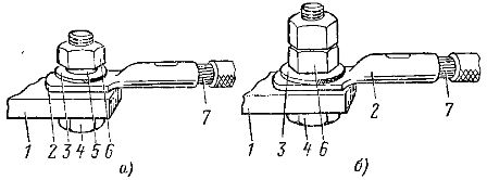
Rice. 3. Connection of a copper conductor with a flat lead made of copper or aluminum alloy: a - for bolts up to M8, b - for all sizes of bolts, 1 - lead, 2 - tip, 3 - washer, 4 - bolt, 5 - spring washer, 6 - nut, 7 - core.
The connection of flat conductors to flat terminals made of copper or aluminum alloy (Fig. 3) is made using steel bolts (GOST 7798-70), nuts (GOST 5915-70) and washers (GOST 11371-78), and to terminals made of aluminum - using contact pressure stabilization means: disc springs or fasteners made of copper or aluminum alloys with a linear expansion coefficient (18-21) x 10-6 °C-1 (Fig. 4).
When assembling a connection with disc springs, an enlarged washer is placed on the side of the aluminum terminal, and a normal washer is placed on the side of the copper tab of the tip. Lock nuts are not used in connections with disc springs.

Rice. 4. Connection of a copper conductor with a flat aluminum terminal: a - using disc springs, b - using fasteners made of non-ferrous metals, 1 - terminal, 2 - copper tip, 3 - spring washer, 4 - steel bolt, 5 - nut steel, 6 - enlarged steel washer, 7 - disk spring, 8 - copper core, 9 - non-ferrous metal bolt, 10 - non-ferrous metal nut, 11 - non-ferrous metal washer.
If disc springs or bolts and nuts made of non-ferrous metals of the required sizes are not available, the connection can be made using an enlarged washer, provided that the contact resistance and heating temperature of the connection are within the specified limits.

Rice. 5. Attaching two lugs to the flat terminal.
In cases where contact connections are operated in a room with a relative humidity of more than 80% and a temperature of at least 20°C or in a chemically active environment, it is made using copper-aluminum transition plates. A direct connection of a copper conductor to an aluminum terminal can be performed in the case where the aluminum terminal has a protective metal coating.

Rice. 6. Adapter parts for connecting more than two lugs to the terminals.
When making a connection to the flat terminal of two cable cores, the lugs should be placed on both sides of the flat clamp (Fig. 5) in order to ensure the lowest transition resistance and maintain a more uniform current distribution. If more than two lugs need to be connected to a terminal or the terminal hole does not correspond to the lug hole, adapter parts are used. The tips are connected symmetrically to the transition piece (Fig. 6).
The connection of flat copper conductors and lugs to pin lugs is carried out using standard nuts made of copper and its alloys. Connections with rated currents up to 30 A are made using steel nuts coated with tin, nickel or cadmium.

Rice. 7. Connecting the tip to the pin terminal: 1 - tip, 2 - enlarged copper nut, 3 - steel nuts, 4 - pin terminal, 5 - core.

Rice. 8. Connection of two lugs with a pin terminal: 1 - lugs, 2 - nuts, 3 - pin terminal.
Aluminum flat conductors at currents up to 250 A are connected in the same way as copper ones, and at currents from 250 to 400 A, enlarged thrust nuts are used for connection (Fig. 7).
The connection of two tips to the pin terminal (Fig. 8) must be done symmetrically, and when connecting more than two tips, adapter parts are used.
For currents of more than 400 A, copper-aluminum lugs should be used or the ends of the busbars should be reinforced (clad).
The connection of round conductors to flat and pin terminals is made after forming them in the form of a ring using star washers. When tightening a screw or nut, the legs of the star washers should not touch the surface of the terminal or the thrust nut so that the core ring is securely pressed to the clamp.
The ring of wire is placed under the head of the bolt or nut so that when the bolts or nuts are tightened, it is not squeezed out from under them (Fig. 9). In cases where the aluminum single-wire core is terminated with a ring tip (piston), the star washer is not used.

Rice. 9. Connection of an aluminum conductor with a cross-section of up to 10 mm2 with leads: a - flat, b - pin, 1 - screw, 2 - spring washer, 3 - star washer, 4 - conductor bent into a ring, 5 - flat clamp, 6 - pin terminal, 7 - nut.

Rice. 10. Connection of a copper conductor with a cross-section of up to 10 mm2 with terminals: a, b - flat, c, d - pin, 1 - screw, 2 - spring washer, 3 - washer, 4 - single-wire conductor bent into a ring, 5 - flat clamp , 6 - pin clamp, 7 - nut, 8 - core terminated with a flat or ring lug.
Copper conductors with a cross-section of up to 10 mm2 are connected to flat and pin terminals using screws, washers, spring washers and nuts (Fig. 10). When connecting cores terminated with a tip (piston), the washer is not used.
Rice. 11. Connection of an aluminum stranded conductor with a cylindrical clamp: a - using a pin tip, b - after fusing the end of the conductor into a monolith with the addition of alloying additives, 1 - body, 2 - clamping screw, 3 - pin tip, 4 - stranded conductor, 5 - the end of the core, fused into a monolith.
With screw terminals for plug-in connection, aluminum or copper stranded conductors can be connected after termination with a pin terminal or after fusing the end of the conductor into a monolith with the addition of alloying additives.
Using this type of connection, all electrical wiring elements are combined into a single structure, both among themselves and with a source of electrical energy.
What is electrical contact?
Electrical contact is the contact of elements that creates continuous operation. electrical network. In other words, an electrical contact is a node through which contact occurs.
How is electrical contact made?
Between conductors, this type of connection is made by pressing one current-conducting element onto another. In this case, bolts, screws, clamps, springs, rivets, joint changes in shape (for example, crimping or twisting), welding, soldering, gluing, etc. are used.
What are the types of contact connections?
All contact connections can be divided into three groups:
1. Non-separable - these connections cannot be disassembled at all without destroying at least one of the parts that forms this connection. Such connections include the following: welded, soldered, riveted, pressed and glued.
2. Collapsible - they can be disassembled into individual elements so that the connected parts remain intact. These are the following connections - bolted, screw and wedge.
3. Detachable - these connections include a plug and socket.
What are the types of contact connections?
Based on this feature, all contact connections are divided into two groups: all-metal with physical welded contact and compression, which are combined into one structure using mechanical contact. In this case, compression connections can be both simple and complex. Simple ones are obtained by connecting conductors that are solid in structure. Complex ones are formed as a result of the connection of a stranded wire and a tip or sleeve, in addition, a complex connection is obtained between two stranded wires.
How are contact connections divided by purpose?
According to the function that contact connections perform in distribution devices, they can be divided into connections, connections and branches.
What should the contact resistance be?
After making the contact connection, the resistance should be such that it is not greater than the similar value of a section of the entire conductor. If such a connection was made from conductors of different materials, then the resistance must be compared with the resistance of the section of the conductor whose conductivity is less.
During use, the resistance of this connection should be no more than 1.8 times the resistance of the entire core.
What are the technologies for producing contact connections?
Currently, there are a number of technologies that produce contact connections between elements through which electric current subsequently passes:
Electric welding by contact heating;
Electric welding using a carbon electrode;
Gas-electric welding;
Gas welding;
Thermite welding;
Contact butt welding;
Cold pressure welding;
Soldering;
Crimping;
Twisting;
Tightening with bolts or screws.
In what cases is electric welding used? with contact heating?
This type of connection is used for terminating, connecting and branching aluminum wires whose cross-section does not exceed 1000 mm2. In addition, this technology is used to connect wires made of different materials - copper and aluminum.
Where is resistance welding using filler materials used?
It is used to connect and terminate aluminum conductors containing several wires, as well as for cables whose cross-section does not exceed 2000 mm2.
In what cases do you resort to electric welding with a carbon electrode?
This technology is used to connect aluminum busbars of a wide variety of sections and configurations.
When is gas-electric welding used?
Most often, this type of connection is used to connect aluminum and copper conductors together.
What are the advantages and disadvantages of gas-electric welding?
The main positive quality of gas-electric welding is that it is performed without fluxes. However, this technology also has a significant drawback - it cannot be performed without fairly expensive equipment, and in this case, expensive gas is used.
Because of this, gas-electric welding is usually used to connect aluminum alloy busbars to copper busbars.
In addition, in order to combine aluminum and copper wire of various sections and configurations, they use gas welding, and in this case, rather inconvenient equipment is used, which takes up a lot of space.
For what applications is thermite welding most suitable?
Thermite welding is used to connect wires made of steel, aluminum and copper. Besides, this method connection is suitable for tires of all sections. It is best to use this type of welding to combine bare power line wires into one system in the field.
In order to carry out such welding, you do not need overly complex and cumbersome equipment. This kind of welding is very simple to carry out, the main problem in this case is that when carrying out thermite welding, the fire hazard increases. There is one more requirement - to carry out thermite welding, it is necessary that thermite cartridges and matches be stored in special conditions. Thermite-crucible welding is used to connect steel strips that make up grounding loops, as well as for installing lightning protection cables.
Where is cold and resistance butt welding used?
Contact butt welding should be used if it is necessary to connect a busbar made of aluminum to a copper one.
Cold pressure welding is used to connect aluminum and copper busbars of medium section. In addition, it is used to connect single-wire wires whose cross-section does not exceed 10 mm2. In order to perform this type of welding, you do not need to use any Additional materials or contact fittings.
Where is soldering used?
Aluminum and copper wires of any cross-section can be connected by soldering. At the same time, this technology is not complicated, and it will not require the use of any complex or bulky equipment, but it will have to cost a lot of money to implement it. a large number of time and effort.
In what cases do they resort to pressure testing?
Crimping is used to make a contact connection for aluminum, steel-aluminum and copper wires, both insulated and non-insulated. The cross-section of such wires is up to 1000 mm2. When making terminations and connecting conductors, you need to very carefully and carefully select tips, sleeves and punches with dies.
It is permissible to twist wires only if they will be used on communication lines. The choice of contact connection technology directly depends on what materials need to be connected to each other, on their cross-section, voltage, shape, as well as on installation conditions.
How to prepare a conductor for a contact connection?
In this case, preparation directly depends on the technology that will be used to make the contact connection. Let’s say that when using soldering, the ends need to be cut in steps or at an angle of 55°. This is done so that contact occurs between the tubular part of the sleeve and the wires on each side.
When using termination or connecting sector or segment cores using special tools, the wires must be rounded using pliers. This is done so that the core easily fits into the cavity of the sleeve.
The contact ends of flat conductors that need to be welded should be straightened, and the edges should be processed.
How to obtain reliable contact between the connected conductors?
In order for such contact to be as tight as possible, they should be thoroughly cleaned of films. In this case, you need to use rinsing, chemical dissolution of films that may be on the metal. It is quite acceptable to resort to mechanical cleaning. Quite often, all these cleaning methods are used together.
However, it is quite effective to use mechanical cleaning in combination with rinsing and dissolving. The method by which the surface will be cleaned must be selected depending on what materials the elements being connected are made of. It is also necessary to pay attention to whether they have protective coatings made of metal, to types of films, and it is also necessary to take into account the technology by which this contact connection will be made.
The easiest way to clean the surface is mechanically. This is done by cleaning with steel brushes or brushes made of card tape. Aluminum contact surfaces must be cleaned as thoroughly as possible. First, you need to apply a special protective lubricant to the surface. It is best to use technical Vaseline for this purpose. This is done to ensure that the surface of the joined elements does not oxidize again.
If the surface is covered with a layer of oil film, it must first be degreased using solvents. The conductor is then cleaned using a mechanical method until it reaches a mirror-like shine.
How to protect the surface from re-contamination?
To prevent the surface from becoming contaminated again, it must be additionally protected. In this case, protection must be selected depending on which contact connection will be used. The degree of protection is also influenced by the material from which the conductors are made and the conditions in which the connection will be located.
Let's say, when carrying out contact welding or soldering, the surface must be protected from oxidation using fluxes. When using a bolted connection, crimping or twisting, they are protected from oxidation with the help of contact lubricants.
What should contact lubricants be characterized by?
These substances must have a high degree of adhesion. From a chemical point of view, they should be neutral, but physical qualities their main characteristic is elasticity.
Protective contact lubricants can be: process or condenser petroleum jelly, quartz petroleum jelly paste. It is worth noting that these lubricants are applied to the surface in a thin layer.