Shut-off valve assembly drawing. Examples of drawings of typical assembly units. An example of detailing a drawing of a general view of the “Valve” assembly unit
 1. Design of drawing 1. 1. Basic inscriptions. Form of main inscriptions Main inscriptions are determined by GOST 2. 104 68, which establishes their shapes, sizes, and the procedure for filling out the main and additional columns. The main inscriptions are located in the lower right corner of the drawing. On sheets of format A 4, the main inscriptions are located only along the short side 1. 2. The order of filling out the main inscriptions In the columns (column numbers are indicated in brackets) the main inscriptions indicate: in column 1 - the name of the product and the name of the design document, if it is assigned a code; in column 2 - designation of the document; in column 3 - designation of the material (the column is filled in only on drawings of parts); in column 4 - the letter assigned to this document (for training drawings the letter “U”);

 Sealing rings The soft sealing rings are fastened to the shut-off valve using a nut and washer. At constant temperatures, a metal ring can be attached to the body of the body by pressing (a). In case of frequent temperature changes, to ensure a long service life of the valve, the rings are made of copper alloys carried out by deforming the body or ring, made in the form of a double-sided or single-sided dovetail (b). Fastening o-rings to threads (a) is used when the metals of the rings are of increased or high hardness and cannot be flared. In these cases, the ring is also fastened by deforming the metal of the body or bolt itself (b).
 Valve. The valve mount on the spindle head must allow the valve to rotate freely. For valves of small passages (diameter up to 50 mm), fastening with a spindle crimp can be used. wire clamp wire ring fastening the spindle head in the valve slot
 Valves mounting options for large passage valves are shown in the figure below. Directing the movement of the valve in the body and eliminating its displacement or misalignment is achieved using three or four upper or lower guide ribs.
 The gland seals in the fittings between the spindle and the cover are made with soft packing. The packing is pressed by a union nut, a threaded bushing (Fig. a, b) or a stuffing box cover (Fig. c, d). The stuffing box cover is fastened with studs, behind mounting bolts with a T-shaped head (Fig. c) or hinged bolts (Fig. d). In Fig. and the stuffing made of hemp or linen cord is shown, in Fig. b - packing from individual rings (asbestos plate, leather, rubber, etc.). The union nut and stuffing box are shown in the raised position on the assembly drawings. a c b d
 Flywheels. Methods for attaching flywheels to a spindle are shown in the figure below. For fittings of small passages, instead of fastening with a nut, riveting is allowed.

 Grooves for the exit of the grinding wheel. Grinding allows you to obtain precise surfaces of parts. The edges of the grinding wheel are always slightly rounded, so the groove for the exit of the grinding wheel is made in that part of the part where the presence of a ledge remaining from the edge of the grinding wheel is undesirable. Such a groove in the drawing of the part is depicted in a simplified manner, and the drawing is supplemented with an extension element showing the profile of the groove. The types, shape and dimensions of grooves are established by GOST 8820 - 69. The determining size for grooves on surfaces of revolution is the surface diameter d. The dimensions of the grooves are not included in the dimensional chains of parts.
 Grinding along the outer cylinder (A) Grinding along the inner cylinder (B) d b External grinding d 1 Internal grinding d 2 R R 1 Up to 10 1 1.6 d – 0.3 d + 0.3 0.5 0.2 Up to 10 Sv .10 to 50 2 3 d – 0.5 d + 0.5 1.0 0.3 0.5
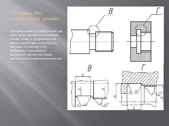 Grooves for metric threads. A groove is made at the end of the thread to allow the tool to exit and obtain a full profile thread along the entire length of the rod or hole. In the drawings of the part, the groove is depicted in a simplified manner and the drawing is supplemented with an extension element on an enlarged scale.
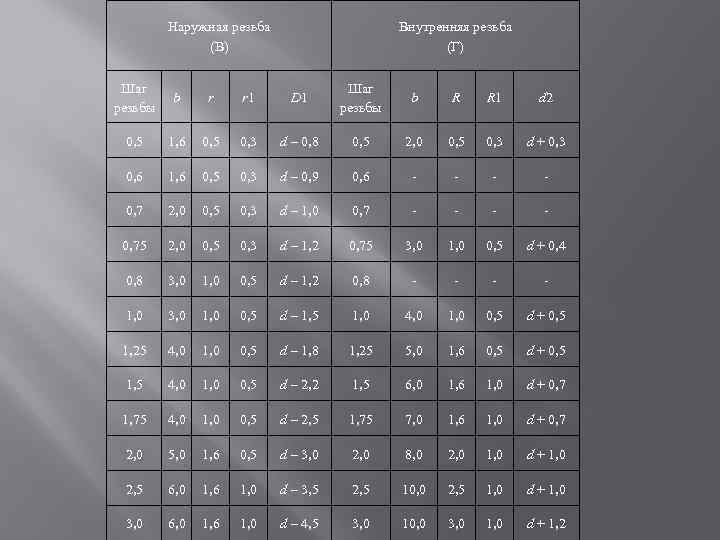 External thread (B) Internal thread(D) Thread pitch b r r 1 D 1 Thread pitch b R R 1 d 2 0.5 1.6 0.5 0.3 d – 0.8 0.5 2.0 0.5 0.3 d + 0.3 0. 6 1. 6 0. 5 0. 3 d – 0. 9 0. 6 0. 7 2. 0 0. 5 0. 3 d – 1. 0 0. 7 0. 75 2. 0 0. 5 0 , 3 d – 1. 2 0. 75 3. 0 1. 0 0. 5 d + 0. 4 0. 8 3. 0 1. 0 0. 5 d – 1. 2 0. 8 1. 0 3. 0 1, 0 0, 5 d – 1, 5 1, 0 4, 0 1, 0 0, 5 d + 0, 5 1, 25 4, 0 1, 0 0, 5 d – 1, 8 1, 25 5, 0 1.6 0.5 d + 0.5 1.5 4.0 1.0 0.5 d – 2.2 1.5 6.0 1.6 1.0 d + 0.7 1.75 4 , 0 1. 0 0. 5 d – 2. 5 1. 75 7. 0 1. 6 1. 0 d + 0. 7 2. 0 5. 0 1. 6 0. 5 d – 3. 0 2. 0 8, 0 2, 0 1, 0 d + 1, 0 2, 5 6, 0 1, 6 1, 0 d – 3, 5 2, 5 10, 0 2, 5 1, 0 d + 1, 0 3, 0 6, 0 1, 6 1, 0 d – 4, 5 3, 0 10, 0 3, 0 1, 0 d + 1, 2
 Measuring a part A wide variety of measuring instruments are used to measure parts. Let's look at techniques for measuring parts using simple tools such as a steel ruler, calipers, calipers and bore gauges.
 Measurements using a caliper Caliper is the most common measuring tool, allowing you to take measurements with an accuracy of 0.1 mm. They can measure the diameters of the rollers, the diameters of the holes, the width of the grooves and slots, the depth of the holes and various recesses, etc. The caliper consists of two main parts (Fig. 18): a ruler (bar) and a frame that covers the ruler. The ruler has a millimeter scale. The frame has a scale called vernier. This scale has 10 divisions. A narrow depth gauge ruler is rigidly attached to the frame. The frame with the depth gauge can move freely relative to the rod, and can also be fixed in any position using a clamping screw. Both the rod and the frame have two jaws, allowing for external (lower jaws) and internal (upper jaws) measurements (Fig. 19). In any position of the frame relative to the rod, the distance between the working upper and lower jaws is equal to the length of the elongated part of the depth gauge. To establish the size measured by a caliper, you need to read on a ruler the number of whole millimeters that fall within the leftmost division of the vernier (zero stroke of the vernier). Then determine which order of the vernier stroke coincides with the ruler stroke, which corresponds to the number of tenths of a millimeter. In our example, the relative position of the ruler and vernier scales, highlighted in Fig. 18, corresponds to size 22.7 mm.
 Measurements using a bore gauge and calipers The diameter of a hole located deep inside the part is measured with a bore gauge with an accuracy of 0.5 mm. The distance between the legs of the bore gauge is determined using a steel ruler. In cases where it is impossible to remove the caliper without disturbing its installation, the wall thicknesses can be measured (with an accuracy of 0.5 mm) as shown on the right. In this case, the legs of the caliper are moved apart a little more than the thickness of the wall being measured, for example by 25 mm. Having now measured the distance between the legs of the caliper, subtract 25 mm added to the wall thickness from the resulting value, i.e. a = 37 25 = 12 mm. To measure the center-to-center distance of holes of the same diameters, use calipers or bore gauges, applying them to the walls of the holes. The required distance will be equal to the sum of the measured distance and the diameter of one of the holes. If the diameters of the holes are different, then half the sum of the diameters must be added to the distance between the nearest walls of the holes. The height of the part can be measured using two rulers.
 To determine the radii of curvature of the protrusions and depressions of the part, radius gauge templates are used (Figure 22, a). A set of radius templates is enclosed in a metal casing. On one side of the casing there are templates with rounded protrusions, intended for determining the radii of the depressions, and on the other side, templates with the same depressions for determining the radii of the protrusions. The radius value is indicated on each template. Larger fillets, as well as flat fillets, can be made by making an imprint on paper, by placing it on the rounded part of the part and crimping or outlining the outline of the fillet with a finely sharpened pencil. Using a compass, determine the radius of the rounding. The resulting size is rounded to the nearest normal radius according to GOST 6636-69. Parts often contain elements with threads, for the measurement of which special templates called thread gauges are used. They are a set of metal plates with protrusions corresponding to the thread profile. On the thread gauge housing, M 60° is indicated for metric threads (Fig. 22 b), and for pipe threads D 55°. Measuring the thread pitch consists of selecting a template whose teeth completely fit into the recesses between the threads. Then, using a caliper, measure the outer diameter of the thread of the rod (nominal thread diameter d) or the diameter of the thread cut from the hole along the protrusions (internal diameter of the thread –d 1. For example, the caliper showed the diameter of the rod thread 21.6 mm, and the thread measures for metric threads pitch 0 , 75. Using the tables of ST SEV IBI 75, we determine the thread: M 22 x0, 75. In the absence of a thread gauge, the technique shown in Fig. 23 is used. In this case, the thread is painted with a soft pencil lead and rolled on paper. The thread pitch is determined as follows: P = A/n, where A is an arbitrary distance between several strokes, n is the number of distances between strokes in size A, and n is less by one than the number of strokes.

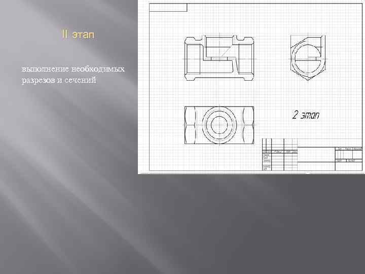
 Stage I is determined by the required number of types, drawing the outline of the part without observing the scale, but adhering to the proportions

 Valve. Drawing general view. An example of a general view drawing Drawing dimensions on a general view drawing On training drawings, dimensions are indicated in font No. 5, and position numbers in font No. 7 or No. 10. The main inscription is the same as on sketches 55 x 185 - form No. 1. On training drawings of general types, the following dimensions must be applied: 1. Overall dimensions, determining the largest dimensions of the product in length, width, height. 2. Dimensions of mating surfaces (on which parts come into contact assembly unit), including threaded surfaces. 3. Installation dimensions by which this product is installed at the installation site. 4. Structural and design dimensions, determined by the peculiarities of the work of the part in the assembly. Characteristics of gears, springs, center distances, modulus, etc. and other parameters required by the detailer. Free dimensions are not applied to general views, since these dimensions are taken directly from the drawing, taking into account scale. General arrangement drawings are not production drawings. 5. Connecting dimensions. Dimensions that define the elements by which this product is connected to another. These dimensions include: a) diameters of holes for fasteners; b) dimensions of connecting threads, etc.

Ministry of Education and Science of Ukraine Sevastopol National Technical University ASSEMBLY DRAWING. TRAINING SKETCHES OF UNIT PARTS Guidelines to complete individual assignments in engineering graphics for students technical specialties full-time and part-time forms of education Sevastopol 2009 Create PDF files without this message by purchasing novaPDF printer (http://www.novapdf.com) 2 UDC 744 Assembly drawing. Training sketches of assembly parts. Guidelines for completing individual assignments in engineering graphics for full-time and part-time students of technical specialties. / Comp. A.F. Medved, V.G. Sereda, A.I. Dubovik. – Sevastopol: SevNTU Publishing House, 2009. – 32 p. The guidelines contain brief explanations necessary for making sketches of the parts included in the assembly, as well as an assembly drawing of the assembly and drawing up a specification. The guidelines are intended for technical specialties of full-time and part-time students. Methodological instructions were approved at a meeting of the Department of Descriptive Geometry and Graphics, protocol No. 6 dated January 16, 2009. Approved by the educational and methodological center of SevNTU as methodological instructions. Reviewer: Smagin V.V., Associate Professor, Candidate of Sciences tech. Sciences Create PDF files without this message by purchasing novaPDF printer (http://www.novapdf.com) 3 1. 2. 3. 4. 5. 6. 7. CONTENTS INTRODUCTION…………………………… ………………………... Purpose and content of the task………................................... ................ Compilation block diagram unit……………………………... Execution of sketches of parts of the unit...….……………………….. Execution of a technical drawing of the part…………………… Execution of an assembly drawing of the unit …..…………………..... Execution of the specification…..…………………………………….. Questions for self-control………………………………… …. CONCLUSION…………………………………………………………… REFERENCES………………………… 3 3 4 5 19 24 27 30 30 31 INTRODUCTION A node is a detachable or permanent connection components products. In the educational process for a unit (for example, a tap or valve), the following is performed: – sketches of the parts of the unit; – assembly drawing of the unit; – specification. An assembly drawing of a unit is a document containing an image of an assembly unit and other information necessary for its assembly (manufacturing) and control. Training sketches of a unit are made in design (training general view) or technological (training assembly drawing) versions. The training assembly drawing should give an idea of the location and interconnection of the parts included in the assembly. The assembly drawing of the unit indicates the item numbers of the parts, overall, installation and connection dimensions. 1. PURPOSE AND CONTENT OF THE TASK Purpose: – acquisition and consolidation by students of practical skills in sketching parts from life, measuring parts, putting dimensions on sketches and performing technical drawings; – study of GOSTs: 2.108-68 – Specification, basic requirements for the execution of assembly drawings and 2.109-73 – Basic requirements for drawings; – acquisition of practical skills in drawing up an assembly drawing of a unit and filling out specifications. Create PDF files without this message by purchasing novaPDF printer (http://www.novapdf.com) 4 Contents of the task: – make sketches of the parts included in the assembly (with the exception of standard ones); – draw an assembly drawing of the unit; – draw up a specification in accordance with GOST 2.108-68. 2. DRAFTING A STRUCTURAL DIAGRAM OF A UNIT Full-time students receive a unit at the department in accordance with the individual option, and part-time students choose a unit independently and present it along with the completed work. The assembly must include at least four parts, excluding standard parts and materials. To complete the task, you must: – become familiar with the design of the unit, establish the purpose and principle of its operation; – disassemble the assembly into its component parts and reassemble it in the reverse order; – draw up a diagram of dividing the product into its component parts; – assign a name to the unit and its components; As an example, a diagram of a straight-through valve with a nominal bore of 15 mm has been drawn up. The general view of the valve and its section are shown in Figures 1a, b. a) b) Figure 1 Create PDF files without this message by purchasing novaPDF printer (http://www.novapdf.com) 5 We disassemble the valve into its component parts: – unscrew nut 12, remove washer 14 and flywheel 10; – unscrew the union nut 5 and remove the oil seal bushing 6; – unscrew fitting 3 from body 1 together with rod 4, valve 2, sealing gasket 9, nut 11 and washer 13, stuffing box 15 and support ring 7; – remove the sealing gasket 8 between the fitting and the body; – unscrew the rod with the valve, sealing gasket, nut and washer from the fitting; – remove the stuffing box seal 15 and support ring 7 from the fitting; – unscrew nut 11, remove washer 13 and sealing gasket 9; – disconnect rod 4 and valve 2. The components of the unit (parts and material) are presented in Figure 2. The diagram for dividing the product into its component parts is shown in Figure 3. The valve includes four standard parts: two nuts and two washers, as well as material - hemp. Thus, for this valve it is necessary to sketch ten parts. 3. SKETCHING THE DETAILS OF AN ASSEMBLY A sketch is a temporary drawing made by hand on a visual scale in compliance with proportions. Sketches of parts and technical drawings are made in pencil on paper in A4 or A3 format. Completed sketches and technical drawings are bound into an album. A sample title page is shown in Figure 4. The following sequence of sketch execution is recommended: – selection of the main type and number of images of the part; – selecting a sheet format and drawing images of the part; – drawing extension and dimension lines; – measuring the part and setting dimensional numbers; – application of signs and roughness parameters (may not be included on training drawings); – determination of the grade of material; – filling out the main inscription; – checking the sketch. In the title block of the drawing, the name of the product is written in nominative case singular. In a name consisting of several words, a noun is placed in the first place, for example, “Union nut”. Create PDF files without this message by purchasing novaPDF printer (http://www.novapdf.com) 6 Figure 2 Create PDF files without this message by purchasing novaPDF printer (http://www.novapdf.com) 7 Feed valve M6 nut GOST 5915- 70 Flywheel Washer 6 GOST 11371- 78 Fitting Union nut Stuffing sleeve Gasket Stem Valve Gasket Nut M5 GOST 5915- 70 Washer 5 GOST 11371- 78 Support ring Hemp PS GOST 5152- 66 Housing Figure 3 Examples of execution and design of e sketches of details are given in Figures 5...14. Depending on the design of the connection between the stem and valve parts, their shapes may vary slightly. Figures 15a,b show the types of connections between the stem and the valve. Figures 15a, b show examples of making threads on the shank of a rod with a thread run-out and with a groove for the cutter to come out for attaching the flywheel with a nut. The groove dimensions are selected according to GOST 10549-80 depending on the thread pitch. Figure 15c illustrates the design of the rod shank, intended for fastening the flywheel with a screw. Create PDF files without this message by purchasing novaPDF printer (http://www.novapdf.com) Ï Î ËÜÑÊÈÉ Í ÀÖÈÎ Í ÀËÜÍ ÛÒÅÕÍ È×ÅÑÊÈÉ ÓÍ ÈÂÅÐÑÈÒÅÒ Êàôäðà í à÷åðòàòåëüí î é ãåî ì åòðèè è ãðàôèk ÀËÜÁÎ Ì ÝÑÊÈÇÎ Â ÊÇÀÄÀÍ ÈÞ “Ó× ÅÍ ÛÅ ÝÑÊÈÇÛ ÄÅÒÀËÅÓÇËA. ÑÁÎ ÐÎ ×Í ÛÐÒÐÒÅÆ" VÂûï î èë èë: ñòäåí ò òã ð. ÈÌ - 21ä Èâàí åí êî À.Ï . ¹ ça÷åòí î é êí èæêki 070374 Ï ðîîâåðèë: äî öåí ò Ï åòðåíî À.È. SUMMARY 2009 Figure 4 Create PDF files without this message by purchasing novaPDF printer (http://www.novapdf.com) 9 Figure 5 Create PDF files without this message by purchasing novaPDF printer (http://www.novapdf. com) 10 Figure 6 Create PDF files without this message by purchasing novaPDF printer (http://www.novapdf.com) 11 SNTU.701400.004 9 7 1.6o450 2 chamfers M6 9 M12x1.5 R1 5 0 8 13 42 75 SNTU .701400.004 Letter Change. Sheet Document No. Signature Date Ivanenko 10/15/08 Developed. Checked by Petrenko T.kontr. Weight Mass. Piece Sheet Sheets Kaf. NGiG gr.IM-21d N.kontr. Approved Figure 7 Create PDF files without this message by purchasing novaPDF printer (http://www.novapdf.com) 12 Union nut Figure 8 Create PDF files without this message by purchasing novaPDF printer (http://www.novapdf.com) 13 SNTU.701400.002 Valve Figure 9 Create PDF files without this message by purchasing novaPDF printer (http://www.novapdf.com) 14 A- A A A SNTU. 701400.010 Flywheel AK12 GOST1583-93 Figure 10 Create PDF files without this message by purchasing novaPDF printer (http://www.novapdf.com) 15 SNTU.701400.009 Gasket Rubber GOST 7338-90 Figure 11 Create PDF files without this message by purchasing novaPDF printer (http://www.novapdf.com) 16 SNTU.701400.008 Gasket Rubber GOST 7338-90 Figure 12 Create PDF files without this message by purchasing novaPDF printer (http://www.novapdf.com) 17 SNTU.701400.003 36 15 11 1.6 45° 9 10 6 30° 25 3° M20 1.5 14 1.5 14 M12 ° 45 M20 1.5 2 chamfers 1 45° 7 24 13 22 SNTU.701400.003 Liter. Sheet Document No. Signature Date Developed. 10/15/08 Ivanenko Checked by Petrenko T.control. N.cont. Approved Weight Mass. Fitting Leaf Br. OTS 4- 4- 4 GOST 5017- 74 Sheets Dept. NGiG gr.IM-21d Figure 13 Create PDF files without this message by purchasing novaPDF printer (http://www.novapdf.com) Figure 14 ÑÍ ÒÓ.701400.001 18 Create PDF files without this message by purchasing novaPDF printer (http:/ /www.novapdf.com) 19 Valve Stem Valve Stem a) b) Figure 15 a) b) c) Figure 16 4. PERFORMING A TECHNICAL DRAWING OF A PART In the task, students perform a technical drawing of a part in rectangular isometry with a cutout of one quarter. The technical drawing can be done together with the part sketch on one sheet or on a separate format. In the first case, the location of the axes of the technical drawing must correspond to the location of the axes of the part (Figure 17). If the technical drawing is made on a separate sheet, then the location of the axes in the technical drawing does not depend on the location of the axes in the sketch (Figure 20). The sequence of constructing a technical drawing of the “Case” part is presented in Figures 18...20. The construction of isometric projections of parts is carried out in the following sequence: – construct in thin lines the axonometric axes and all the lines of the external and internal contours lying in planes parallel to the OXY and OYZ planes (Figure 18); – construct lines of the external contour of the part and sections of the part using projecting planes passing along the OX and OY axes, i.e. cut out the fourth part of the part - (Figure 19); – remove invisible lines and lines of the cut part of the part and hatch the section (Figure 20). Create PDF files without this message by purchasing novaPDF printer (http://www.novapdf.com) Figure 17 P. 701400.001 20 Create PDF files without this message by purchasing novaPDF printer (http://www.novapdf.com) 21 Figure 18 Create PDF files without this message by purchasing novaPDF printer (http://www.novapdf.com) 22 Figure 19 Create PDF files without this message by purchasing novaPDF printer (http://www.novapdf.com) 23 SNTU. 701400.001 Figure 20 Create PDF files without this message by purchasing novaPDF printer (http://www.novapdf.com) 24 5. EXECUTION OF AN ASSEMBLY DRAWING OF AN ASSEMBLY An assembly drawing is a drawing containing an image of an assembly unit (assembly) and other data necessary for its assembly and control during assembly (GOST 2.102-68). The assembly drawing is made on an A2 sheet using sketches of parts previously completed by the student, checked by the teacher, as well as drawings of standard parts and materials included in this assembly taken from the reference book. The assembly drawing must contain: – an image of the assembly unit with the necessary views, sections, sections and the main inscription; – instructions on the connection method (if necessary); – position numbers of the components of the assembly; – dimensions: overall, installation, connection, controlled and reference. A sample assembly drawing is shown in Figure 21. Let's consider the sequence of drawing the assembly drawing of a bushing valve. 1. Install required amount images (types, sections, sections). To visualize the design of a straight-through valve, it is enough to draw a frontal section along the axis of the stem, left view and additional view to the flywheel. In the view on the left, half of the view is combined with half of the profile section. 2. On a sheet of A2 format, using dimensional rectangles, the drawing is broken down. 3. Draw thin lines on both views: 3.1. The main part is the body. Then draw out the fitting together with the sealing gasket. 3.2. Draw out the component moving parts of the product - the rod together with the plate, gasket, washer and screw. Products with moving parts are drawn in a closed position, for example, vices, valves, dampers, and plug valves in an open position. 3.3. Draw out the stuffing box seal - support ring, stuffing box packing, stuffing box bushing and union nut. The gland packing fills the space between the rod and the fitting from the support ring to the top of the fitting. The packing is sealed using a stuffing box and a union nut. The conical surfaces provided on the support ring and the lower part of the stuffing box bushing, when screwing the union nut, press the stuffing box against the rod. 3.4. Draw out the flywheel and the parts attaching the flywheel to the rod - a nut and washer. The flywheel is drawn in the main view and top view. Create PDF files without this message by purchasing novaPDF printer (http://www.novapdf.com) Figure 21 25 Create PDF files without this message by purchasing novaPDF printer (http://www.novapdf.com) 26 4. Outline contour lines with a thickness of 0.6...0.8 mm and shading in sections and sections with lines with a thickness of 0.3...0.4 mm. Adjacent parts made of the same material are hatched in different directions or with a change in the distance between the dashed lines. 5. Mark overall and connection dimensions. 6. Draw leader lines and mark the part position numbers on the shelves of the leader lines. Position numbers are placed in such a way that they are located on one (or several) verticals, on one (or several) horizontals, or on horizontals and verticals. 7. Fill out the main inscription, indicate (if necessary) technical requirements or technical characteristics products. 8. The product specification is completed on a separate sheet. The assembly drawing is carried out with conventions and simplifications: – in views and sections it is allowed not to indicate such elements of parts as chamfers, fillets, grooves, recesses and others small elements; – the heads of bolts and nuts having a hexagonal shape are made in a simplified manner; – the slots of the heads of screws and screws are shown as one solid thick line; – projections of lines of intersection of curved surfaces can be drawn in a simplified manner if their precise construction is not required. For example, instead of pattern curves, you can draw circular arcs; - a smooth transition from one surface to another is shown conditionally or not shown at all; - solid or standard parts - bolts, screws, studs, nuts, washers, balls, wedges, etc. are shown in a longitudinal section without being dissected; – stiffening ribs of parts (spokes of flywheels, gears) and thin walls in a longitudinal section are shown unshaded; – the edges of a square hole or rod are marked with solid thin lines drawn along diagonals. Create PDF files without this message by purchasing novaPDF printer (http://www.novapdf.com) 27 Pos. Zone Format Name Designation Qty. Note 8 15 5 6. EXECUTION OF SPECIFICATIONS Specification is Text Document , which determines the composition of the assembly unit (assembly) necessary for manufacturing, completing design documents and planning the launch of the specified products. The specification is drawn up for each assembly unit, complex and kit on separate A4 sheets according to form 1 (title sheet) and 1a (subsequent sheets). The dimensions of the specification and title block according to form 1 are shown in Figure 22 and for form 1a - in Figure 23. 6 6 8 70 63 10 22 185 5 8x5=40 Meas. Develop Sheet Check Document no. 15 10 Signature Date 03.22.03 N.control. Approved Designation Name Product letter 5 55 Sheet 15 Sheets 20 55 23 15 7 10 Pos. Zone Format Name Designation Qty. Note 8 15 5 Figure 22 6 6 8 70 63 10 22 185 23 15 10 Sheet Meas. Sheet No. document. Signature Date Designation Figure 23 Create PDF files without this message by purchasing novaPDF printer (http://www.novapdf.com) 8 7 555 7 10 28 The specification contains seven columns: “Format”, “Zone”, “Pos.”, “Designation”, “Name”, “Quantity.” and “Note” and is filled out in the following sections: – documentation (indicate the assembly drawing); – assembly units (if they are included in the unit); – details (write down all the details of the assembly for which sketches were drawn up, in the nominative case, singular); – standard parts; – materials (enter data on the materials used). The specification columns are filled in as follows: – in the “Format” column, indicate the format of the documents, the designation of which is written in the “Designation” column. The column is not filled in for documents recorded in the “Standard Products” and “Materials” sections; – in the “Zone” column indicate the designation of the zone in which the assembly drawing is located if the drawing field is divided into zones; – in the column “Pos.” indicate the serial numbers of the component parts of the product in accordance with the sequence in which they are recorded in the specification; – in the “Designation” column indicate: in the “Documentation” section - the designation of the documents being recorded, for example, SNTU.702700.000SB, and in the sections “Assembly units”, “Parts”, “Kits” - the designations of the main design documents for the products recorded in these sections , for example, SNTU. 702700.001; – in the “Name” column in the “Documentation” section, write down the name of the documents, for example, “Assembly drawing”. In the sections “Assembly units”, “Parts”, “Kits” indicate the name of the products in accordance with the main inscription on the main design documents of these products. In the “Standard Products” section the names and designations of products are indicated in accordance with the standards for these products. In the “Materials” section – designation of materials in accordance with standards and technical specifications for these materials. – in the column “Quantity.” indicate the number of components included in one specified product. In the “Materials” section, record the amount of materials per product, indicating the unit of measurement. – in the “Note” column, write down additional information about the components of the product. After each section, several free lines and positions are left. An example of a completed specification is shown in Figure 24. Create PDF files without this message by purchasing novaPDF printer (http://www.novapdf.com) Pos. Zone Format 29 Col. Note Name Designation Documentation A2 SNTU.701400.000SB Assembly drawing Parts A3 A4 A4 A4 A4 A4 A4 A4 A4 1 2 3 4 5 6 SNTU.701400.001 SNTU.701400.002 SNTU.701400.003 SNTU.701400.00 4 SNTU.701400.005 SNTU.701400.006 7 SNTU.701400.007 8 SNTU.701400.008 9 SNTU.701400.009 10 SNTU.701400.010 Body 1 Valve Fitting Stem Union nut 1 1 1 1 1 1 1 1 Oil seal sleeve Oil seal ring Gasket Gasket Flywheel 1 Standard products 11 1 Nut M5.5.0 18 GOST5916- 70 Nut M6.5.018 GOST 5915- 70 12 13 1 1 Washer S.5.01.08kp.018 GOST 11371- 78 Washer S.6.01.08kp.018 14 1 GOST 11371- 78 Materials Hemp PS GOST 5152- 66 0.02 kg 15 Meas. Develop Sheet Check T.cont. N.cont. Approved Document no. Signature Date 10.22.08 Ivanenko Petrenko SNTU.701400.000 Letter Valve Sheet 1 Dept. NGiG gr.IM-21d Figure 24 Create PDF files without this message by purchasing novaPDF printer (http://www.novapdf.com) Sheets 1 30 7. QUESTIONS FOR SELF-CHECK 1. What should the assembly drawing contain? 2. What is the sequence of completing an assembly drawing of a product from life? 3. What simplifications are allowed in assembly drawings? 4. What dimensions are shown on assembly drawings? 5. How are the components of a product marked on an assembly drawing? 6. What is a specification? 7. What products are specifications drawn up for? 8. List the specification columns. CONCLUSION As a result of completing the task, students should know: – GOST 2.305-68 – Images: views, sections, sections; – GOST 2.307-68 – Drawing dimensions; – GOST 2.311-68 – Image of thread; – GOST 2.312-72 – Conditional images and seam designations welded joints; – GOST 2.313-82 - Symbols and symbols of permanent connections; – GOST 2.317-69 – Axonometric projections; – GOST 2.108-68 – Specification; – GOST 2.109-73 – Basic requirements for drawings; be able to: – make sketches and technical drawings of assembly parts from life; – carry out assembly drawings and fill out specifications. Create PDF files without this message by purchasing novaPDF printer (http://www.novapdf.com) 31 REFERENCES 1. Geometric drawing with rules for drawing design: Guidelines for independent work in the discipline “Descriptive geometry, engineering and computer” graphics for full-time and part-time students / Comp. A.F. Medved, V.G. Sereda, N.Ya. Smirinskaya. – Sevastopol: SevNTU Publishing House, 2005. – 38 p. 2. Kovtun V.N. Reference materials for making drawings of instrumentation and mechanical engineering: Handbook / V.N. Kovtun. – Sevastopol: SevNTU Publishing House, 2002. – 132 p. 2. Levitsky V.S. Mechanical engineering drawing and automation of drawings / V.S. Levitsky. – M.: Higher. school, 2001. – 429 p. 3. Guidelines on the rules for drawing dimensions for students’ independent work when performing individual tasks / Comp. A.F. Medved, L.N. Ivashchenko. – Sevastopol, 1989. – 25 p. 4. Mikhailenko V.Є. Engineering and computer graphics: handy. for students vyshchih zakl. illuminate / V.Є. Mikhailenko, V.V. Vanin, S.M. Kovalov; per ed. V.Є. Mikhailenka. – K.: Karavela, 2003. – 344 p. 5. Descriptive geometry and drawing. Engineering graphics. Guidelines for the course and test assignments for students of engineering specialties of correspondence education / Comp. A.M. Preris [et al.]. – Kharkov: UZPI, 1986. – 151 p. 6. Popova G.N. Mechanical engineering drawing: Reference. / G.N. Popova. – L.: Mechanical Engineering, Leningrad. department, 1986. – 447 p. 7. Drawing up a drawing of a product from nature. Guidelines for independent work in the discipline “Mechanical Engineering Drawing” / Comp. M.N. Logunenko, L.V. Galkina, L.I. Maksimovsky. – Sevastopol: KMU SPI, 1988. – 48 p. 8. Reference guide to drawing / V.A. Bogdanov [and others]. – M.: Mashinostroenie, 1989. – 864 p. 9. Training sketches and drawings of parts. Guidelines for completing individual assignments in engineering graphics for full-time and part-time students of technical specialties. / Comp. A.F. Medved, V.G. Sereda. – Sevastopol: SevNTU Publishing House, 2009. – 40 p. 10. Reading and detailing a general drawing. Guidelines for students' independent work. / Comp. L.V. Galkina. – Sevastopol: SevGTU, 1998. – 28 p. 11. Sketches and drawings of parts. Guidelines for completing assignments in the course “Descriptive Geometry and Engineering Graphics” / Comp. V.G. Sereda. – Sevastopol: KMU SPI, 1990. – 22 p. Create PDF files without this message by purchasing novaPDF printer (http://www.novapdf.com) 32 Order No. _____from “____” _________________Circulation _______copies. SevNTU Publishing House Create PDF files without this message by purchasing novaPDF printer (http://www.novapdf.com)
Many parts have standard sizes. Therefore, when indicating their numerical values in the drawing of a part, the resulting actual dimensions are rounded to the nearest standard, using the normal range of linear dimensions and diameters (GOST 6636-69*), standard sizes of radii of roundings and chamfers (GOST 10948-64*), tapers and slopes ( GOST 8593-81), normal angles (GOST 8908-81), “turnkey” (GOST 642473*), threads, keyways, grooves for the exit of the thread-cutting tool, etc.
On the detailed POC, some elements of the parts are shown in a simplified, conditional way or not shown at all, which does not allow their design to be revealed. This is usually expressed in the absence of casting and stamping slopes, chamfers, undercut threads when cutting them point-blank, a simplified display of blind holes with threads, grooves and grooves for the exit of a thread-cutting or grinding tool, etc. On the working drawing, such elements should be shown without simplifications completely, unless specifically stated in the standards. Moreover, most of these structural elements in their shapes and sizes are determined by the relevant GOSTs, which should be used when detailing.
14.4. An example of detailing a drawing of a general view of the “Valve” assembly unit
To complete the example, a detailed drawing is given - the valve's CVD (see Fig. 14.1), its specification (Fig. 13.10) and the description of the detailed product given below.
A valve is a type of fitting designed to regulate the flow of liquid (usually water) in a pipeline and to shut off pipelines.
The liquid is supplied to the valve through the left threaded hole of housing 1, and the outlet is carried out through the right one. The valve shut-off device consists of a valve 4 and a rod 3, connected with the possibility of their free rotation relative to each other. In the drawing, the valve is shown closed: valve 4 closes the passage hole in housing 1 with a diameter of 40 mm, connecting the inlet and outlet. The valve is opened by moving the valve with the stem upward while rotating the latter in the threaded part of the cover 2 using a flywheel 6 mounted on the stem with a screw 8. By lifting the stem with the valve higher or lower, the cross-section of the passage hole and the fluid flow through the valve are changed.
Pos details 6 and 7 not shown |
|
Letter 27 |
|
Compress |
|
Yes. line 4
B(2:1) äåò. ïîç. 3 |
|||
All sizes are for reference. |
|||
40.02.013.000 ÂÎ |
|||
ÌÀÄÈ(ÃÒÓ) ãð. ...
To eliminate leaks between the body and the cover, use a gasket 7, and between the rod and the cover - an stuffing box seal consisting of a packing 9 and a threaded bushing 5.
Materials of parts pos. 1, 2, 5 - bronze BrOTsS3-12-5 GASÒ 613-79, parts pos. 3, 4 - brass Ë62 GASÒ 15527-70*, parts pos. 6 - aluminum alloy ÀË2 GÎÑÒ 2685-75, parts pos. 7 - Cardboard A GOST 9347-74.
The results of the first stage of reading the CHOV are as follows:
1. The CHOV, made on a scale of 1:1, shows a valve - a product related to pipeline valves (see the main inscription of the drawing).
2. According to the specification, the valve consists of seven parts (body, cover, stem, valve, bushing, flywheel and gasket), one standard product (screw) and material (hemp fiber) for packing the stuffing box.
3. Familiarity with the CHOV and the description of the valve made it possible to understand its purpose (in principle, the purpose of any valve is to retain or pass liquid), the general structure and principle of operation.
4. On the CHOV, in projectional connection with each other, three are given
images of the valve: frontal (longitudinal) section (main image), top view and connection of the halves of the left view and profile (transverse) section. The sections reveal the internal structure of the entire product and its individual parts. The frontal section, top and left views reflect the external shape of the valve and most of its components. Note that the non-hollow rod 3 is not dissected in the sections, and the threaded hole in it is shown in a local section of the rod.
The shape of the flywheel, in particular, the number of spokes and their cross-section, is explained by the view À of the flywheel and the extended cross-section of the spoke placed next to it. The shape, location and number of valve ribs 4 are revealed by its appearance Á. The shape and dimensions of the non-standard thread in parts 2 and 3 are revealed by the extension element Â.
In total, the valve RAF is represented by seven images.
5. For CHOV 120, 72, 180...200 - overall dimensions; G1 1/2, 60 (spanner size for connecting the valve) - installation and connecting dimensions; 40 (diameter of the passage hole in the valve), 135...155 (distance from the axis of the pipelines to the most
remote point of the valve), 70 (size of the handwheel that controls the valve), G1 1/2, M52x2 and thread dimensions on the remote element B are dimensions that cannot be determined from the drawing. There are no installation and operational dimensions for the CHOV.
In the drawing there are inscriptions on the shelves of the leader lines: “3 ribs” - indicating the number of valve ribs 4; “Wrench size 27” - wrench size for tightening the bushing 5; “ Crimp during assembly” - indication of the connection of valve 4 and rod 3 during assembly; “Lap in” is an indication of processing when assembling the adjacent surfaces of valve 4 and body 1.
6. Housing 1 is used to place and install other valve parts in it or on it and connect it to the hydraulic system. The cover 2 ensures the translational movement of the rod 3 during its rotation and the placement of an stuffing box seal in it, which prevents liquid leaks between the cover and the rod. The rod moves valve 4 translationally. The valve closes and opens the through hole of the housing connecting the underwater and outlet pipelines. Bushing 5 is a pressing and fastening device for the stuffing box seal. Flywheel 6 rotates the rod. Gasket 7 is used to eliminate liquid leaks between the body and the cover. Screw 8 secures the flywheel to the rod. The stuffing box packing 9 is a sealant for the stuffing box seal.
The fixed detachable connections of the valve are the threaded connection of the body 1 with the cover 2 and the connection of the rod 3 with the flywheel 6 with a screw 8.
The stem head 3 is secured in the valve bore 4 by compressing the edges of the bore (one-piece connection). In this case, the stem head is placed in the valve bore with a gap that allows the valve to be centered relative to the body opening being closed and to rotate freely relative to the stem.
The rod 3 is screwed into the cover 2 by means of a thread and, when rotated, can move in the axial direction relative to it (movable detachable connection). When the stem is fully screwed in, the associated valve rests against the body and closes the valve.
Bushing 5 is screwed into the threaded hole of cover 2 and has the ability to be screwed into it as the oil seal packing wears out.
into the hole in cover 2; Place gasket 7 on the threaded outer part of the cover and screw the cover into body 1 with a wrench; fill the stuffing box of the cover between the latter and the rod with the stuffing box (pos. 9); sleeve 5 is put on the rod and screwed into the cover, pressing the stuffing box; A flywheel 6 is mounted on the upper part of the rod and secured to the rod with a screw 8.
Let us recall that the amount of stuffing box in the stuffing box should be such that during assembly, sleeve 5 is wrapped in cover 2 by 2 - 3 turns, tightly compressing the stuffing box.
When disassembling, unscrew screw 8 and separate flywheel 6 from rod 3; unscrew sleeve 5 from cover 2 and remove the sleeve from the rod; use a wrench to unscrew the cover from housing 1; unscrew the rod from the cap. Valve 4 is not separated from the stem during disassembly.
Having received a general idea of the valve structure and the shapes of its components, at the 2nd stage of reading the FAQ, the shapes of all elements of the valve parts are determined in detail and thoroughly. Let's consider the process of identifying the shapes of parts using the example of a rod.
According to the specification, the rod is assigned position 3, by the number of which the image of the rod is found on the main image of the valve. To do this, find the number 3 above the shelf near this image. The leader line extending from this shelf ends with a point on the desired image of the rod.
Using the relationship of images, other images of the stock on the CHOV are found. In total, there are 4 images of the stem: the main image of the valve basically reveals the shapes of all elements of the stem; the top view and the image on the profile projection plane reveal the shapes of the rod elements onto which the flywheel is placed; Extension element B specifies the shapes and dimensions of the stem element with non-standard threads.
The material of the rod is brass, grade L62, from which a rod blank is obtained by injection molding, which is then subjected to mechanical processing.
Analysis and comparison of all images of the rod on the CHOV, taking into account its purpose and connections with other parts installed at the 1st step of reading the CHOV, showed that the rod is an axisymmetric part, all elements of which, with the exception of one,
formed by outer surfaces and located along a common axis in the following sequence:
- the stem head, formed by spherical compartments, cylindrical and conical surfaces of rotation and used to connect the stem to the valve;
- an element with a non-standard external cylindrical thread connecting the rod to the cover and ensuring reciprocating movement of the rod;
- cylindrical element connecting the rod head and the element
threaded;
- a cylindrical element extending from the threaded element, protruding from the cover and allowing the rod to be acted upon externally by means of a flywheel;
- an element for putting on the flywheel rod, formed by four flats made at the end of the previous cylindrical element;
- a blind hole with a standard metric thread for fixing the flywheel to the rod with a screw, which is the only internal element of the rod.
The mating surfaces of the rod are both threaded surfaces, the surfaces of the flats and the head of the rod. The free surfaces of the rod are the surfaces of its cylindrical elements.
Blind hole with a thread in the rod is shown in a simplified way on the CHOV without a conical chamfer at the beginning of the threaded hole and without taking into account the supply of thread in the hole and its undercut, which must be taken into account when making a working drawing of the rod.
In a similar way, the shapes of other valve parts were studied and understood.
After finishing reading CHOV ( preparatory stage), proceed to the execution and execution of working drawings of parts in the order set out, as already noted, in section 12.
An analysis of the design, shapes and sizes of parts carried out when reading the valve’s FOC showed that it is advisable to carry out working drawings of the body and cover in A3 formats, and the remaining parts in A4 formats.
The design of the body, manufactured by casting with subsequent processing of part of its surfaces on machines, is shown in the working drawing (Fig. 14.2, scale 1:1) by a frontal longitudinal section, the connection of the halves of the top view and the horizontal longitudinal section, and the connection of the halves of the left view and the cross section


section (Fig. 14.2). In educational settings, a horizontal longitudinal section is often not performed, being limited to a top view. The main image of the housing is positioned so that the axis of its inlet (supply) and outlet (outlet) holes is horizontal, and the axis of the hole for the cover is vertical, and the inlet hole should be on the left, the outlet on the right, and the hole under the cover is directed upwards. In this hole, the working drawing shows a chamfer that is not visible on the CHOV.
The shape of the lid, also made by casting, is reflected (Fig. 14.3, scale 2:1) the main image is the connection of the halves of the front view, on which three edges of the outer prismatic surface are visible, and the front longitudinal section, displaying a through hole with smooth and threaded surfaces, and See also the left view to clarify the shape of the prismatic surface and set the turnkey size. In addition to these two images, for convenience, on the extension elements the shape of the groove for the exit of the thread-cutting tool and the shape and dimensions of the non-standard thread are specified. Note that on the CHOV the groove is shown in a simplified manner, and there are no chamfers in the threaded holes at all. The axis of symmetry in the main image of the cover can be horizontal
13 18 Á

zontal, as in Fig. 14.3, or vertical. In the first case, A3 format is used for the working drawing horizontal arrangement, and in the second - vertical location, on
which instead of the left view is given a top view. |
|||||
The shape of the rod is revealed (Fig. 14.4, |
|||||
scale 1:1) its main view from the ground - |
|||||
incision to display the deaf |
|||||
threaded holes and top view for |
|||||
sizing on a turnkey basis, additionally |
|||||
for convenience, part of the view is traced |
|||||
va, on which two flats are visible for |
|||||
landing of the flywheel, and remote elements |
|||||
fragment |
non-standard |
||||
threads. Blind hole with thread on |
|||||
the working drawing is shown without simplification |
|||||
ny. Main stock picture can |
|||||
be positioned horizontally (Fig. |
|||||
since the stock is basically |
|||||
formed by coaxial |
surfaces |
||||
rotation. Vertical |
|||||
location |
main type |
||||
rod (Fig. 14.4), which is caused by |
|||||
more rational |
using |
||||
drawing fields and wide use |
|||||
We eat machines with vertical processing |
|||||
surfaces of revolution. |
|||||
On the valve drawing (Fig. 14.5, |
|||||
scale 1:1) two of them are shown |
|||||
images: main view with local |
|||||
cross-section to show the valve bore and left view to reveal the shapes and placement of the ribs. In the main view, the valve occupies a horizontal position with the ribs pointing to the left so that the maximum number of ribs is visible (two for this valve). The valve in the working drawing is shown in the state in which it arrives for assembly - before it is pressed onto the stem head.
*Size for reference.
and the dimensions of the groove for the exit of the thread-cutting tool, shown in a simplified manner on the CHOV. The gasket on the working drawing can be shown with a horizontal position of the axis as a part formed by surfaces of rotation, or with a vertical position of the axis, which it occupies when cutting a hole in it in the mold.
Figure 1.22 shows an assembly drawing of a valve, the body of which and some parts are made by casting. The valve specification (first sheet and subsequent sheet) is presented in Figures 1.23 and 1.24.
Figure 1.25 shows an assembly drawing of a valve with a welded body; The flywheel of this valve is a reinforced product. The valve specification is shown in Figure 1.26.
Drawings of taps with a conical plug are shown in Figures 1.27 and 1.29, and specifications for them are shown in Figures 1.27 and 1.30, respectively. In the first case, the sealing force on the plug is created by the oil seal bushing using bolts, and in the second case, by a spring.
Figure 1.32 shows a drawing of a valve with a ball plug. The specification for it is shown in Figure 1.31.
Figure 1.12 – Drawing of the assembly unit “Spindle”

Figure 1.13 – Working drawing of the “Spindle” part

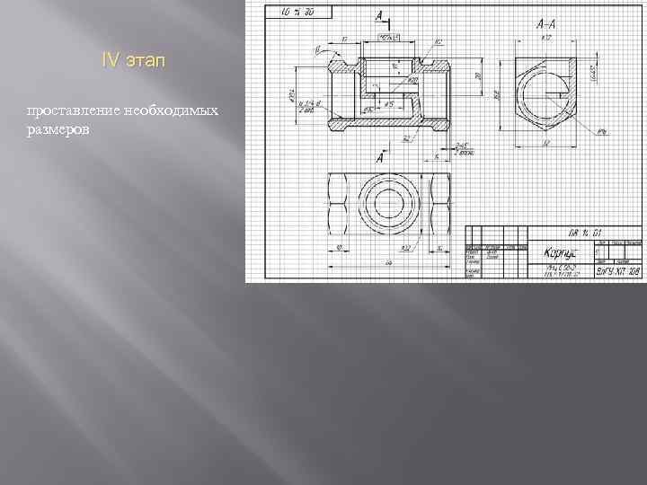
Figure 1.14 – Working drawing of the “Valve” part

Figure 1.15 – Drawing of a welded assembly unit

Figure 1.16 – Drawing of a reinforced product

Figure 1.17 – Cover. Working drawing
 Figure 1.18 – Union nut. Working drawing
Figure 1.19 – Handle. Working drawing


Figure 1.17 Valve body. Working drawing

Figure 1.21 Valve body. Working drawing


Figure 1.22 – Valve. Assembly drawing.


Figure 1.23 – Valve. Specification

Figure 1.24 - Valve. Specification. Sheet 2
 Figure 1.25 – Assembly drawing of a valve with a welded body

 Figure 1.26 – Valve. Specification

Figure 1.27 – Plug valve. Specification

Figure 1.28 – Plug valve. Assembly drawing

 Figure 1.29 – Crane. Assembly drawing.

 Figure 1.30 – Plug valve. Specification
 Figure 1.31 – Ball valve. Specification
 Figure 1.32 – Ball valve. Assembly drawing

CONTROL QUESTIONS
1. Formulate the definition of an assembly drawing.
2.What dimensions are shown on the assembly drawing?
3.How do you choose the number of images and the main image on an assembly drawing?
4. Why do you agree on the dimensions of the mating surfaces before completing the assembly drawing?
5. What detail do you start with for the main image?
6. List the permitted simplifications and conventions on the assembly drawing. What is their purpose?
7. In what position are the valve spool and the valve plug shown?
8. What does it mean to “read” an assembly drawing?
9. What is the purpose of the specification?
10. What is meant by part position?
11. Define an assembly unit.