What is the cable entry for? How to choose a cable gland. Metal cable glands
In everyday life or at work, we use electricity, and where there is an external sealed connection to electrical equipment, we cannot do without cable glands. Sealing is essential when working with electricity to ensure safety.
Various cable entries are used to enter wires into stationary equipment, and they are also relevant in electrical equipment, which can be moved and then fixed. This product is also called a cable gland, sealed lead-in. It protects the wiring from mechanical damage and from penetration of moisture and dust.
What is important to know about the products
Pressurized lead-ins consist of the following parts:
- frame;
- petal clamp;
- seal;
- union nut;
- thread sealant;
- counter nut.
The seal ensures the tightness of the product. The union nut clamps the wire. The counter nut secures the cable entry to the equipment housing.
The main parameter of the gland is the cable thickness (from 1 mm). The second most important parameter is dust and moisture resistance (IP54 - no protection, IP68 - maximum protection). The maximum pressure difference may be specified, as well as the maximum and minimum possible temperatures.
Threads used:
- M - metric;
- PG - inch;
- NPT - pipe.
Based on the material used, sealed leads are divided into:
- plastic;
- metal.
Plastic products are most widespread due to their ease of manufacture and, as a result, low cost. They are mainly made from polyamide. Fireproof material is used to withstand high temperatures.
Metal cable glands are structurally no different from plastic parts, except that the body and nuts are made of metal.
The following metal alloys are used:
- nickel plated brass;
- stainless steel.
ASIS 400 stainless steel is used for corrosive environments.
In explosive production, explosion-proof seals are relevant. Such fittings are the most reliable, and under no circumstances should an explosive mixture get inside the equipment.
Explosion-proof bushings come in two types:
- for armored cables;
- for unarmored cables.
Entries for armored cables have different designs compared to the second option. A product of a certain design is suitable for each wire. The input model must match the type of armor.
It is impossible to imagine the modern world without various electrical appliances. They make our work easier, help automate some processes, and monitor various indicators in real time. The heart of any device is printed circuit board, with electronic components, connectors and modules located on it, which are susceptible to mechanical stress and the environment. To protect them, a sealed housing is used, and cable glands are used for external sealed connections.
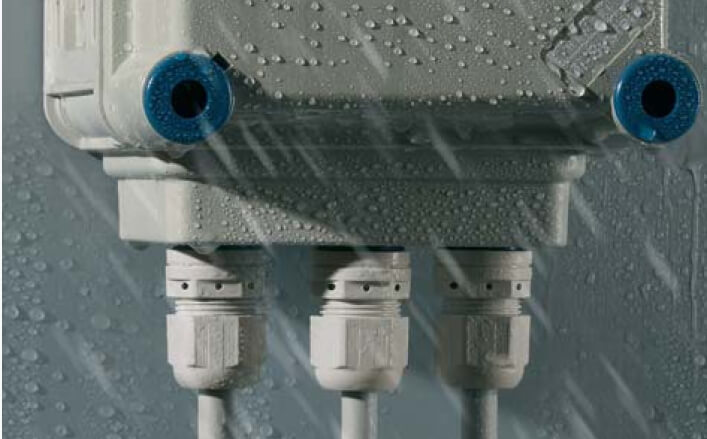
Junction box with connected cable entries
Components
Cable entry components:
- frame,
- spade cable clamp,
- cable gland,
- union nut,
- thread sealer
- counter nut.
Seals provide the necessary degree of protection against the penetration of moisture and solid particles. The union nut secures the cable with a spade clamp. The mating nut is used to clamp the sealed gland onto the device body or simply screw it in if there is a threaded hole in the body.

Main settings
The main parameter is the cross-section of the clamped cable. There are entries for thin cables (1-3mm) and for large diameter cables (up to 70mm). The next important parameter is the degree of protection against penetration (dust and moisture protection). It happens in the range IP54 (without protection from external influences) - IP68 (protection from jets of water at a depth of 1 meter). The main electromechanical characteristics are: withstand pressure difference, without loss of tightness (usually up to 5 Bar) and operating temperature range (depending on the material of manufacture and the type of pressure seal, it ranges from −60 to +100C)
Cable entry thread type:
- M - Metric threads, standard M12-M63 (but there are series with non-standard sizes threads from M6 to M100
- PG - Inch thread, standard PG7 - PG48
- NPT - Pipe thread, standard 1/2'' to 4''
Range
Today, the range of cable glands, glands and sealed glands is extensive and includes hundreds of models and thousands of modifications.
Plastic cable glands
The most common are standard plastic bushings. The material used to manufacture such glands is polyamide 6. The cable gland can also be made of fire-resistant polyamide 6, certified for fire safety class V0-UL94. The cable gland is made of TPV (Thermoplastic vulcanizates), the thread seal is a rubber ring NBR (nitrile butadiene rubber) of round or flat section.

Selection of plastic sealed leadsOrtac
Special notches can be made on the inside of the union nut to prevent unscrewing due to vibration loads. Such bushings can provide a high degree of protection up to IP68, protection against oils and alkalis.
Metal cable glands
The design of standard metal bushings does not differ from plastic ones. The housing of the cable gland and union nut is made of metal:
- Nickel-plated brass Grade MS58 (brass 58%, zinc 52%) / MS63 (brass 63%, zinc 37%)
- Stainless steel . The ASIS 300 series is used (Chrome-nickel stainless steel, the most versatile). The ASIS 400 series is also used (stainless steel with a high chromium content - retains its properties in corrosive and sulfur-containing environments, resistant to sudden temperature changes)

Metal cable glands and accessories
Typically, the seals for metal cable glands are NBR and TPV, but there are series of metal glands with silicone seals. As standard, a polyamide 6 spade clamp is used in the metal cable gland.
Types and types of cable glands
|
| With blind rubber band (plastic only)- the cable entry is equipped with a plastic membrane (gasket) and can maintain the tightness of the housing without a pulled cable. To install the cable, you only need to pierce the gasket. |
|
| With wire protection- inputs with spiral protection of the cable from breaking. The union nut is made with a spiral at the end. These bushings are used in devices experiencing vibration loads or mechanical impact For additional protection cable from breaking. |
|
| Multi-hole (plastic and metal)- are used if it is necessary to stretch several wires of small cross-section through a sealed lead-in. The range of wire sections is from 3 to 9 mm. Provides protection - IP65 (dustproof, protected against jets of water) |
| Flat cable entries (plastic and metal)- used to insert a flat cable into a sealed housing, the cable width can be from 13 to 45 mm, height from 7 to 14 mm. Provide protection - IP65 |
|
| With flat nut (plastic and metal)- for less demanding applications there is a series of cable glands with a flat nut. Without a thread seal, the cable gland provides protection IP54, with a seal - IP65. |
|
|
| With wire clamp (metal only)- There is also a series of metal cable glands with a clamp. This series can be used to protect the cable from movement due to mechanical stress. |
|
| EMC inputs (metal only).- For shielded cables there is a specially developed EMC series of cable glands. This series is designed for electromagnetic shielding of cable input by grounding to the shielding braid of the cable. Grounding is provided by special petals of the sealed lead-in, which reliably clamp the cable braid. |
|
| Extra-large section (metal only)- For very large cable cross-sections there is a series of metal cable glands in extra-large sizes from M63×1.5 to M90×2.0 |
|
| Mini cable glands- For applications in confined spaces, mini series cable glands can be used. The range of series sizes is from M6×1.0 to M12×1.5. The range of cable sections is from 2 to 8 mm. Provides IP68 and can be equipped, in addition to standard ones, with EPDM seals or silicone seals. |
|
| Ventilation cable glands- a line of seals for equalizing pressure in sealed housings and protecting against condensation. Models have holes on the body and a hydrophobic membrane inside. Such a design provides air exchange, but does not allow moisture to pass through, thereby maintaining IP68 of the entire device. |
|
| Entries with silicone seal (metal only)- equipped with a silicone gasket, which provides a wider temperature range for the cable gland while maintaining IP68: from −60 to +200 C |
|
| Glands protected from microorganisms (metal only) are carried out in accordance with the US Department of Health directive on “use of equipment in medical and food equipment" The design of the inputs makes them difficult to dirty and facilitates cleaning, and a special membrane (TPE) prevents germs and bacteria from entering the device |


A separate category of metal bushings for use in hazardous areas. The key purpose of a pressure seal in such conditions is not to protect against explosion, as it might seem at first glance, but to prevent the penetration of flammable gases into the device. The sealed lead-in must not allow gas leakage between the seal and the cable sheath. Consists of a housing, a union nut, one or two cable glands, a threaded seal and a counter nut.

EX and accessories
In Russian practice, explosive zones are divided into several types depending on the presence in this zone of a highly flammable substance or dust, which forms an explosive mixture together with air.
Zone 0 (Zone 20) Explosive gas (dust) is present continuously or for an extended period of time
Zone 1 (Zone 21) - Explosive gas (dust) is not constantly present, but there is a possibility of its occurrence under normal operating conditions
Zone 2 (Zone 22) - Explosive gas (dust) can only appear as a result of equipment operating errors or breakdowns and is present for a short time

Varieties
- Cable entry for armored wire with double seal
- Cable entry for armored wire with one seal
- Standard cable entry for unarmored wire
- Cable entry for unarmored wire for pipe systems
- Cable entry for armored wire with a flat nut.
To operate bushings in explosion-proof conditions, they must be certified according to international (ATEX standard) and Russian (compliance with technical regulations TR TS 012/2011) requirements.
The functionality and capabilities of cable glands can be expanded through the use of various accessories:
- Threaded/cable plug, placed in place of the cable entry in the junction box to cover the hole. Maintains the IP of the device body in the absence of a cable entry. If necessary, it can be quickly dismantled/the plug can be made of polyamide or metal.
- Counter nut with and without collar, polyamide 6
- NBR/TPV O-ring seal
- Reducers and threaded adapters, nickel-plated brass
- For explosion-proof models also used
- Threaded plugs with different heads, for a socket wrench, with a round head for a hexagon, recessed under a hexagon. (brass, nickel-plated brass or stainless steel)
- Threaded adapters and reducers (brass, nickel-plated brass or stainless steel)
- Protective casing, fits over the sealed lead-in for additional protection TPV, PVC, LSF
- Ground contact, for glands for armored cables, MS64 nickel-plated brass or stainless steel
|
|
|
|
|
|
|
|


Accessories for cable entries
Major cable gland manufacturers
As in most cases in the electrical market, cable gland manufacturers are divided into 2 groups. European ones set the technological pace, certify products and develop specialized solutions for industries. Colleagues from Asia skillfully copy all developments, avoid sanctions for patent infringement and offer more low prices. But there are exceptions.
Main European manufacturers:
- (Germany, main specialization - industrial and explosion-proof seals for hazardous areas. High price segment. Leading manufacturer on the market)
- (Germany, major manufacturer cable and wire products and accessories for general industrial use. High price segment)
- Wiska(Germany, specialization in a standard line of cable glands. Adaptation of products to Russian GOSTs. High price segment)
- (Germany, Production of cable glands is a separate division. The entire standard line of glands. High price segment)
- Bimed(Finland-Turkey. apologist for solutions for the food and medical industries. Middle price segment)
- Ortac (Turkey, Full line of cable glands, including EMC, explosion protection, general industrial glands and Corrugation. In Russia, they are actively developing the OrVent brand - ventilation solutions for sealed enclosures. Despite the wide range and the availability of the necessary certificates, they adhere to a low price segment - at the level of Asian analogues )
CNC turning and milling machines for metal processing (left) thermoplastic automatic machines for the production of plastic products (right) at Ortac production
Major Asian manufacturers
(China, standard line of sealed leads, the main feature is a wide range of sizes within standard models, including NPT threaded entries. Middle price segment)
(Taiwan, in addition to the standard line, there are solutions for miniature metal sealed leads. Expensive brand, high price segment)
IEK(De jure Russian, de facto - Chinese manufacturer of connectors and electrical components. Low price segment)
(China, narrower line of bushings, mainly for distribution boxes. Low price segment)
Cable glands are widely used in industry, in particular in such industries as lighting engineering, security and safety, laying and installation of electrical networks, and telecommunications. Metal models are used in heavy industry - oil and gas complex, shipbuilding. A variety of shapes, types and sizes allow you to choose an effective solution for any task
Usage: laying cables through walls, floors, descendants of input or bushing insulator structures. The essence of the invention: the device contains a cylindrical housing 1 embedded in the concrete wall of the reactor compartment of a nuclear power plant, to the ends of which flanges 2 and 3 with conical threaded holes 4 are welded for installation of sealing units. Each sealing unit includes a sleeve 5 with a cone-shaped diaphragm shell 6 installed inside it, the wall of which is corrugated. The shell 6 is filled with a sealing compound 7 with conductors 8 of the cable 9 passing through the latter, having sections 10 with the insulation removed. The corrugated surface of the shell 6 is made along a helical line and corresponds to the pitch internal thread bushing 5, with which it forms a common threaded connection. Sleeve 5 also has an external thread intended for connection with end flanges, for example flange 2, 2 zpf-ly, 1 il. sl s s s s xia yu s
ы „1753528 Al
UNION OF SOVIET
SOCIALIST
REPUBLIC (st) s N 02 G 3/22
STATE COMMITTEE
ON INVENTIONS AND DISCOVERIES
AT THE USSR State Committee for Science and Technology MvShshchr
M 1352578, class. N 02 G 3/22, 1987. (54) CABLE ENTRY (57) Use: laying cables through walls, floors, ceilings of input or bushing insulators. The essence of the invention: the device contains a cylindrical housing 1 embedded in the concrete wall of the reactor compartment of a nuclear power plant, to the ends of which flanges 2 and 3 with conical threaded holes 4 are welded for installation of sealing units. Each sealing unit includes a sleeve 5 with a cone-shaped diaphragm shell 6 installed inside it, the wall of which is corrugated. The shell 6 is filled with a sealing compound 7 with conductors 8 of the cable 9 passing through the latter, having sections 10 with the insulation removed. The corrugated surface of the shell 6 is made along a helical line and corresponds to the pitch of the internal thread; bushing 5, with which it forms a common threaded connection. Sleeve 5 also has an external thread intended for connection with end flanges, for example flange 2, 2 zpf-ly, 1 il.
The invention relates to electrical engineering, in particular to devices for laying cables through walls, floors, ceilings of input or bushing insulators, and can be used when laying control cables through walls nuclear power plants.
A cable gland is known, containing a hollow body with a sealing unit installed in it, made in the form of a cylindrical bushing with holes through which cable cores, filled with a sealing polymer material, pass. Blind holes are made at the ends of the cylindrical bushing of this 15 cable gland, and on its outer surface or grooves are made along the generatrix of the cylinder, or along a helical line, connected to the mentioned blind holes. " 20
However, such a complication of the structural and technological implementation of the formative elements of the sealing unit does not exclude the main disadvantage of the cable gland: shrinkage and peeling phenomena that inevitably arise in the operating conditions of nuclear power plants under the influence of large temperature differences polymer material from the walls of the sleeve and cable conductors, leading to loss of tightness of the input and a decrease in its operational reliability. In addition, replacing a cable input of this design is very labor-intensive, since it requires intervention in the design of the penetration itself. The closest in technical essence and achieved result to the proposed one is a cable gland containing a cylindrical body and end flanges, in the holes of which sealing units are installed, each of which is made in the form of a bushing with a sealing compound placed in it and cable cores passed through the latter, having sections with stripped insulation. The bushings of the sealing units in this device are a massive body with holes for placing individual cable cores. The holes in the bushings are made in two stages, and the diameter is. one stage corresponds to the diameter of the cable wire insulation, and the diameter of the other stage, located on the peripheral sections of the bushing, is greater than the diameter of the cable wire insulation. The gaps between the surface of sections of the cable cores with the insulation removed and the inner surface of the corresponding steps of the bushing holes25
50 cups are filled with adhesive sealing material.
The disadvantage of the known device is its low reliability, since even with this design, due to the natural shrinkage of the polymerizing material, it peels off from the walls of the elements of the sealing unit with the formation of gaps that worsen the tightness of the cable entry.
In addition, during the operation of such a cable gland under conditions of elevated temperatures and radiation, additional polymerization of the sealing material and other negative changes in its structure, including cracking, occur, leading to an additional increase in gaps and practical depressurization of the cable gland, as a result of which there is a need for its emergency replacement directly in the conditions operation. However, although such a replacement is provided for in the known design of the cable gland, it is very complex and time-consuming, since it is associated with the need to replace the end flanges. This is a significant drawback of the known device. The purpose of the invention is to increase reliability while simultaneously improving the repair and restoration ability of the component parts by providing non-destructive replacement when they fail.
This goal is achieved by a cable gland containing a cylindrical body and end flanges, in the holes of which sealing units are installed. each of which is made in the form of a bushing with a sealing compound placed in it and cable conductors passed through the last one, having sections with the insulation removed, equipped with a cone-shaped diaphragm shell located in the bushing, the walls of which are made with corrugations, and the sealing compound is placed inside the shell.
The cone-shaped diaphragm shell can be made of a rigid spring material or an elastic-elastic polymer material.
The drawing shows circuit diagram proposed cable entry.
The cable entry contains a wall embedded in the concrete of the reactor compartment
AE C cylindrical body 1, to the ends of which flanges 2 and 3 are welded with conical threaded holes 4 for installation of sealing units. Each sealing unit includes a sleeve 5 with
1753528 with a cone-shaped diaphragm shell 6 installed inside it, the wall of which is made with corrugations. The shell 6 is filled with a sealing compound 7 with conductors 8 of cable 9 passing through the latter, having sections 10 with the insulation 5 removed. The corrugated surface of the shell 6 is made along a helical line and corresponds to the pitch of the internal thread of the bushing 5, with which it forms a common threaded connection. The bushing 5 also has an external thread intended for connection with end flanges, for example, flange 2. In the proposed cable gland the pitches of the conical threads of all three parts: flange 3, sleeve 5 and shell 6 are made both with the pitches of all threads matching and without their matching, while their taper reaches 2. The cone-shaped diaphragm shell 6 is made of either a hard spring material, for example, structural steel with a given (selected experimentally) wall thinning of up to 0.3-0 5 mm, providing it
25 elastic properties, or from heat-resistant and radiation-resistant polymer elastic material without imposing restrictions on the choice of its wall thickness. With the large base of its cone, shell 6 faces the inside of the body
1, and its height exceeds the height of bushing 5.
The input is also equipped with end caps 11. The assembly and operation of the proposed cable input is carried out in the following manner. First, one of the main elements of the proposed input is manufactured in production conditions - a corrugated shell 6 with 7 cut ends of the cores 8 of the cable 9 filled with a sealing compound. length of a measured piece of cable 9, its ends are cut by removing the insulating sheath from both ends, as well as removing the insulation from the metal cores of the conductors
8 cable 9. The number of bare areas can be from one to several and is determined from the condition of ensuring optimal adhesion of the sealant and the metal conductor (core), since in bare areas the degree of adhesion of the sealant to the conductor increases significantly. Insulation gaps between the bare areas 55. The drains are left for this purpose; so that there is no short circuit. After this, cable 9c is exposed. In separate sections 10 on the cores 8 is inserted into a split mold with a corrugated shell 6 pre-installed in the last one.
The detachable form is compressed with force along the parting line. The sealing composition 7 is poured through special technological holes in the plugs 11 of the shell 6 into the free space between the walls of the said shell 6 and the cores 8 of the cable 9. After polymerization of the sealing composition 7, the mold is disassembled along the parting line: and a similar operation is repeated with the other end of the cable 9.
Upon completion of the technology for preliminary manufacturing and filling of each such cable entry element, the subsequent assembly of the proposed structure is carried out in housing 1 or the embedded pipe of the reactor compartment wall. In this case, from the side of the flange 3 welded to the body 1 (mortgage pipe), a sealing sleeve 5 is screwed onto the conical thread (with a taper angle 2) of the shell 6, the wall of which is made with corrugations, with 7 cores 8 of cable 9 filled with a sealing compound. the conical thread of the shell 6 is simultaneously screwed into the conical thread of the hole in the end flange 3; In this case, the shell 6 with sealant sealed in it with the conductors 8 of the cable 9 and the flange 3 due to the taper angle of the thread within
2O with a different (non-coincident) pitch of all three threads will turn no more than 360-720O. Twisting of the cores 8 of cable 9 practically does not occur with this rotation. With the same (identical) pitch of all three threads, the rotation is significantly reduced and amounts to only 3090°, i.e. cores 8 of cable 9 and flange 3 remain practically motionless; -”:
In the area of flange 2, assembly is carried out in a similar way by screwing the sealing sleeve 5 onto the conical thread of the shell 6, the walls of which are made with corrugations.
When screwing in the threaded parts of the input, due to the elastic deformation of the wall, the internal corrugated surface of the shell 6 is pressed against the surface of the sealing composition 7 in contact with it. With an increase in the contact area and pressure due to the elastic deformation of the elastic crushed wall, adhesion increases to the most optimal values and practically eliminates the possibility of .reduction of leakage due to shrinkage both during the polymerization of the composition and during the entire operational period.
Compiled by A. Yudin
Techred M.MÌrãåítàë
Proofreader O. Kravtsova
Editor M, Yankovic
Order 2771 Circulation Subscription
VNIIPI of the State Committee for Inventions and Discoveries under the State Committee for Science and Technology of the USSR
113035, Moscow, Zh-35, Raushskaya embankment, 4/5
Production and publishing plant "Patent", r. Uzhgorod, st. Gagarina, 101
In addition, in this bushing, compaction of the sealing composition occurs with significant uniformity due to layer-by-layer crumpling of the sealing composition by the corrugations of the elastic wall, which also improves the quality characteristics of the said composition and at the same time increases the tightness and reliability of the cable gland as a whole.
Thus, the proposed design of the cable gland over a long period of operation due to the design features of its constituent parts is maintained in the optimal volumetric volume of the polymerizing sealant, while in cases where any part irreversibly fails, it is replaced, for which The sleeve 5 is unscrewed from the threaded hole of the flange 2, and then the sheath 6 with cable 9 is easily and quickly removed from the sleeve 5.
Installation of a new set of shell 6 with cable 9 is carried out in the reverse order without any intervention in the penetration design. At the same time, the ease and efficiency of installation and dismantling of shell 6 with the conductors 8 of cable 9 sealed in it from the housing 1 of the cable entry is due to the fact that the largest the diameter of the shell 6 is less than the diameter of the holes in the corresponding flanges 2 and 3.
Thus, in comparison with the prototype, the technical and economic advantages of the proposed cable entry lie in the simpler design of the parts that make up the structure; higher operational reliability due to improved sealing by compensating for shrinkage and aging of the sealing composition, higher durability, as well as improving the repair and restoration ability of parts without complicating the design and reducing the labor intensity of installation and dismantling operations due to simplified interconnections of parts. components of the proposed cable gland. The use of the proposed cable gland in the energy sector will dramatically increase the efficiency of maintenance and repair of penetrations for control cables at nuclear power plants.
Except toro. the use of the proposed cable gland at nuclear power plants makes it possible to reduce the permissible level of radionuclide leaks into environment through the containment shell and thereby improve the environmental situation in the nuclear power plant area.
Claim
1. Cable entry containing a cylindrical body and end flanges, 20 in the holes of which sealing units are installed, each of which is made in the form of a bushing with a sealing compound placed in it and cable conductors passed through the latter, having 25 sections with removed insulation, from the bottom which is that, in order to increase reliability while simultaneously improving the repair and restoration ability of the parts making up the structure due to
30 non-destructive replacement when they fail, it is equipped with a cone-shaped diaphragm shell located in the sleeve, the walls of which are made with corrugations, and the sealing compound is placed
35 inside the shell.
2. Input pop.1, except that the cone-shaped diaphragm shell is made of hard spring material.
40 3. Input according to paragraph 1. characterized in that the cone-shaped diaphragm shell is made of elastic polymer material.
Similar patents:
One of the most vulnerable places of any communications is the place where a cable or wire enters the wall of a building, into a switchgear, actuator, etc. Today, there are many options for protecting cable passages from moisture, we have tried to collect the most effective of them for readers site in this article. So, let’s figure out now how cable entries into a building, cabinet, etc. can be sealed.
What standards and requirements exist?
IN regulatory documents Clause 2.1.58 and SNiP 3.05.06-85 describe the requirements for cable passages:

According to the requirements listed above, it turns out that the cable entry in the building must be able to retain water, not support combustion and prevent the spread of fire. With all this, it is possible to re-replace the cable or wire, if necessary.

Sealing methods
To seal the input in a private house or cottage, fire-resistant polyurethane foam is most often used, evenly distributing it in the pipe around the cable. After hardening, the polyurethane foam is cut and partially compacted, pressing it into the pipe. The resulting depression is plastered with cement mortar. An example of such a cable line sealing option is shown in the photo below:

You can also try to use the old-fashioned method: rags cut into thin strips, liquid cement mortar and a piece of rag generously moistened with it are tamped with a wooden stick into the gap between the cable and the pipe.
Another commonly used method is the use of a sealant that fills the unevenness and voids between the hole and the insert sleeve, usually made of fiber cement, metal or plastic. Sealing the cable entry using this method has the advantage that the sealant does not harden, making the entry hole suitable for repair.

In addition, there are specialized professional materials on the market for sealing and production of hermetic bushings. For a sealed passage into a switchboard cabinet or actuator, a sealed cable gland is most often used - a PG gland, shown in the photo below:
A large range of models and different sizes make this decision simple and versatile. The collapsible design of the cable gland allows it to be installed in completely different and convenient places for maintenance. At the same time, the presence of a rubber seal and the correct size of the cable and sealed lead-in will allow achieving high performance tightness, degree of protection IP54-IP68.

It should also be noted that this method of sealing the cable entry is the use of a sealant, which is concreted in the formwork, and a system cover. In appearance, this method of protection looks like this:


There are also specialized seals that allow reliable sealing of the cable entry using inflatable passages, gloves, etc. All these devices, as a rule, are imported, so the cost of this method of protection is quite high. In this case, it is more rational to consider simple, but effective and time-tested options. 
I recently did a boiler room reconstruction project and received a remark from the expert. The expert demanded that I show how I installed the cable into the boiler room building. Nothing complicated should arise here, but I would like to rely on some regulatory documents.
Now I will consider the two most common options for introducing cables into a building or cable structure. The choice of one or another type of cable entry depends on specific conditions.
In this case, we provide a pipe for each cable, for example, asbestos-cement BNT-100. As a rule, cable networks up to 10 kV run at -0.7 m from ground level. Therefore, approximately at this level the cables are introduced into the building. It is allowed to enter cables at a depth of at least 0.5 m and no more than 2 m from the ground surface. When laying pipes, the pipe must be sloped towards the street at an angle of 0.5 degrees. After pulling the cables, all pipes are carefully sealed to prevent moisture and gas from entering the building. The pipe should extend 50 mm into the room. Externally, the length of the pipe depends on the blind area of the building. On average, the length of the pipe is 1.5-2 m. As we can see from the figure, in some cases the pipe can reach up to 5 m. This is exactly the option I had when connecting pumping station, which was in an embankment of earth.

I use this option for introducing cables into a building when introducing power cables into the electrical room of a new building. The pipes are laid during the pouring of the foundation. At the same time, I also provide a pit for introducing pipes from the street, and on this pit I install an input-distribution device. The overall dimensions of the pit depend on the bending radius of the cable and the overall dimensions of the ASU. I almost always add one backup pipe.

I provided this option to the expert, because... I had an existing building and it was unknown what the foundation was there. According to the PUE, up to 2 m we must protect all cables from mechanical damage. In typical projects, in this case, the cables are protected with casings. For small sections, I think it is better to lay the cables in steel pipes. You can use an unperforated metal tray as a casing. When bringing the cable out of the trench onto the wall of the building, we only need to break through a small layer of concrete blind area, and we do not touch the foundation.

This option is suitable for introducing cables into existing buildings.
Regulatory documents for introducing cables into the building:
1 TKP45-4.04-149-2009 (02250). Electrical systems for residential and public buildings. Design rules (clause 16.1, 16.24).
2 SP 31-110-2003. Set of rules for design and construction. “Design and installation of electrical installations of residential and public buildings” (clause 14.1, 14.24).
3 PUE 6. Rules for the construction of electrical installations (clause 2.1.58, 2.1.79, 2.3.32, 7.3.85).
4 Arch. No. 1.105.03tm. Laying power cables with voltage up to 10 kV in trenches (RB).
5 Code A5-92. Laying cables with voltage up to 35 kV in trenches. Issue 1 (RF).