What alternative fuels are there? The use of alternative fuels in aviation gas turbine engines The use of alternative fuels on ships
Due to the presence of several power plants on a large ship, for example, the main engine, a diesel generator for generating electricity, a boiler for producing hot water and steam, marine fuel can be represented by several types at once.
Moreover, main engine A sea vessel is often powered not with one, but with two or more types of fuel alternately. This is due to the fact that in the ocean there are zones of special control of sulfur emissions - the North and Baltic Seas, the Atlantic and Pacific coasts of the USA and Canada.
When approaching them, the engines are switched to diesel fuel with low sulfur content. The same technique is used before performing maneuvers in which it is necessary to frequently change engine modes. After leaving the port, diesel fuel is replaced with fuel oil, on which the ship passes main part ways.
Shipping fuels

The main types of fuel for ships today are:
- diesel fuel;
- high-viscosity marine fuels;
- other types (KST - component of marine fuel from gas condensate, oil gas turbine TG and TGVK, LNG - liquefied natural gas, etc.)
Diesel and low-viscosity fuels are classified as light petroleum products. They differ from each other in cost (SMT is much cheaper), as well as in technical characteristics.
SMT contains more sulfur (from 0.5 to 1.5% versus 0.01%) and has a lower cetane number (40 versus 45). The main benefit when replacing low-viscosity diesel fuel is that the latter is cheap, and also that in the absence of sulfur, special expensive additives must be added to diesel fuel to maintain lubricating properties.
High-viscosity types of marine diesel fuel are classified as dark grades of petroleum products. They are cheaper than light ones, so they are widely used for shipping. They are divided into light, heavy and extra heavy. These types include naval fuel oils F-5 and F-12, heating oils M-40 and M-100, marine fuel IFO-30, IFO-180, IFO-380. They are produced by mixing residual petroleum products with diesel fractions. Dark grades are used in low-speed and medium-speed engines.
On the storage and preparation of marine fuel

To store fuel on a ship, fuel bunkers located next to engine room. A large ship can consume up to 40 tons of fuel per day, but excess fuel, with the exception of emergency reserves in case of storms, is not taken on a voyage, since it creates ballast and reduces the useful load of the ship. Ballast also includes dead fuel on a ship - the remains in the bunkers below the intake pipes.
Before use, fuel oils are often subjected to special preparation operations. They consist of:
- In heating the fuel mass of cold fuel oil, which has lost its fluidity, by adding hot fuel oil to the tank. Heating is also carried out in tanks equipped with special heating systems.
- Cleaning by settling or separation in special ship installations; During these processes, dirt, mechanical inclusions and water are separated. Purified fuel wears out engines less, so purification units more than pay for themselves.
Today there are many types of diesel and other types of fuel for ships. To avoid mistakes when purchasing, try to purchase fuels and lubricants only from trusted suppliers.
© Tishinskaya Yu.V., 2014
The relevance of this topic is determined by the fact that for a vessel to function it needs a large number of fuel, which has a detrimental effect on the condition environment, as huge cargo ships annually release millions of cubic meters of carbon dioxide into the atmosphere, causing enormous damage to the atmosphere and hastening the melting of glaciers at the poles. Also, due to unstable prices for petroleum products and limited reserves of these minerals, engineers are constantly looking for alternative fuels and energy sources.
World shipping is a major source of environmental pollution, as world trade requires great amount consumption of oil and other combustible materials for sea vessels, but as more attention is paid to reducing CO2 emissions, it is clear that the time has come to make changes to the powertrains or find a replacement altogether.
Currently, within just one country, the consumption of motor fuels produced from oil can reach hundreds of millions of tons. At the same time, automobile and sea transport are one of the main consumers of petroleum products and will remain the main consumers of motor fuels for the period until 2040-2050.
Also, a significant impetus for the development of this issue is the fact that, in accordance with the requirements of the International Convention for the Prevention of Pollution from Ships, there is a systematic tightening of requirements for the content of oxides of sulfur, nitrogen and carbon, as well as particulate matter in emissions from sea-going ships. These substances cause enormous harm to the environment and are alien to any part of the biosphere.
The most stringent requirements are put forward for Emission Control Areas (ECAs). Namely:
· Baltic and North seas
· coastal waters of the USA and Canada
· Caribbean Sea
· Mediterranean Sea
· coast of Japan
· Strait of Malacca, etc.
Thus, changes in standards for sulfur oxide emissions from marine vessels in 2012 are 0% and 3.5% in special areas and worldwide, respectively. And by 2020, the standards for sulfur oxide emissions from sea vessels in these areas will similarly be 0%, and worldwide will already drop to 0.5%. This implies the need to solve the problem of reducing chemical emissions into the atmosphere harmful substances ship's power plants and the search for new, more “friendly” types of fuel or energy for use on ships.
To solve these issues, it is proposed to introduce innovations in two various directions:
1) The use of new, more environmentally friendly and economical types of fuel when operating ships;
2) Refusal from our usual fuel in favor of using the energy of the sun, water, and wind.
Let's consider the first way. Main types alternative fuels are the following:
Biodiesel is an organic fuel produced from oilseed crops.
The price of branded biodiesel is approximately two times higher than the price of regular diesel fuel. Studies conducted in 2001/2002 in the USA showed that when the fuel contains 20% biodiesel, the content of harmful substances in the exhaust gases increases by 11% and only the use of pure biodiesel reduces emissions by 50%;
Alcohols are organic compounds containing one or more hydroxyl groups directly bonded to a carbon atom. Alcohols are prohibited as low flash point fuels;
Hydrogen is the only type of fuel whose combustion product is not carbon dioxide;
It is used in internal combustion engines in pure form or as an additive to liquid fuel. The danger of storing it on a ship and the expensive equipment for such use make this type absolutely no fuel not promising for ships;
The water-fuel emulsion is produced on the ship in a special installation - this saves fuel, reduces nitrogen oxide emissions (up to 30% depending on the water content in the emulsion), but does not have a significant effect on sulfur oxide emissions;
Liquefied and compressed combustible gases make it possible to completely eliminate emissions of sulfur and particulate matter into the atmosphere, radically reduce emissions of nitrogen oxides by 80%, and significantly reduce emissions of carbon dioxide by 30%.
Thus, it can be argued that the only new type of fuel, the use of which significantly affects the environmental performance of ship engines, is natural gas.
Let's move on to consider the second way. Wind and sun are the most common sources of energy on earth. Many organizations offer all sorts of projects to implement them in everyday life.
IN international practice There are already several implemented and not yet implemented projects of ships using wind and solar energy for their navigation.
In an effort to reduce fuel consumption on large merchant ships in the world's oceans, a group from the University of Tokyo developed the “Wild Challenger” project.
By using giant retractable sails measuring 50 meters high and 20 meters wide, annual fuel consumption can be reduced by almost 30 percent. For maximum thrust, the sails are individually controlled and each sail is telescopic with five tiers, allowing them to be stowed away when the weather turns unfavorable. The sails are hollow and curved, made from aluminum or reinforced plastic, making them more wing-like. Computer modeling as well as wind tunnel tests have shown that this concept capable of working even in cross winds. Thus, the “Wind Challenger” project can truly become the development of fuel-efficient ships of the future generation.
The company “Eco Marine Power” has developed a project “ Aquarius", which means "Aquarius". A special feature of this project is the use of solar panels as a sail.
Such sails even received their own name “rigid sail”. They will become part of a large project that will allow seagoing vessels to operate without problems. alternative sources energy while at sea, on the roadstead and in the port. Each sail panel will automatically change position using computer control, which is being developed by a Japanese company. KEI System Pty Ltd" The panels can also be removed during adverse weather conditions.
The latest advances in solar technology mean that it is now possible to use a combination of solar panels and sails, a fact that this project to the forefront in the development of modern shipbuilding.
System " Aquarius» is designed in such a way that it does not require much attention from the ship's crew and is relatively easy to install. The materials from which the rigid sail and other system components are made are recycled.
System " Aquarius» will become attractive for investment by shipping companies and ship operators due to quick payback project
We can conclude that both of these ways are designed to solve the same problems. The implementation of these projects has a significant impact on global shipping, contributing to a significant reduction in environmental pollution and reducing fuel and maintenance costs. What to choose is everyone’s business. An easier way for implementation is to use economical fuel, since this technology does not require complete replacement fleet, and can be used on existing ships, but still maintains a certain level of fuel costs and emissions of harmful substances into the atmosphere. The choice in favor of building ships that use alternative energy sources in their operation, on the one hand, requires a complete replacement of the fleet, but on the other, eliminates fuel costs and significantly reduces different kinds environmental pollution.
Literature
1. Sokirkin V.A. International maritime law: textbook / Sokirkin V.A.,
Shitarev V.S. – M: International relationships, 2009. – 384 p.
2. Shurpyak V.K. Application alternative types energy and alternative
fuels on sea vessels [Electronic resource]. - Document access mode:
http://www.korabel.ru/filemanager
3. Ships of the future [ electronic resource]. – Document access mode:
http://korabley.net/news/korabli_budushhego/2010-04-05-526
4. Economical ships are possible [electronic resource]. – Access mode
document: http://korabley.net/news/ehkonomichnye_suda_vozmozhny/2014-01-06-
5.Alternative Aquarius System Could Change Shipping
[electronic resource]. – Document access mode: http://shipwiki.ru/sovremennye_korabli/na_ostrie_progressa/alternativnaya_sistema_emp_aquarius.html
Over the past twenty years, the automotive industry has made enormous progress in reducing the content of harmful substances in exhaust gases. Ban on the use of leaded gasoline, the use of exhaust gas catalytic converters and modern systems power supply of internal combustion engines, allowed to significantly reduce the harmful effects road transport on the environment and human health.
During the operation of automobile internal combustion engines, not only toxic gases are emitted into the atmosphere, but also carbon dioxide (CO 2).
Modern car engines have become more fuel efficient, resulting in lower carbon dioxide emissions. The use of alternative fuels also helps to both reduce harmful substances in exhaust gases and reduce the amount of carbon dioxide.
Liquefied petroleum gases(LPG - Liquefied Petroleum Gas) make it possible to reduce the content of harmful substances in exhaust gases and at the same time reduce by approximately 10% the amount of CO 2 emitted during internal combustion engine operation.
Compressed natural gas(CNG - Compressed Natural Gas) is an alternative fuel that can be used in spark-ignition internal combustion engines and diesel engines. To be used as fuel in an internal combustion engine, it must be compressed to high pressure to take up less space. This gas can be transported in high pressure cylinders. When used as fuel, it ensures a reduction in emissions of harmful substances into the atmosphere.
Methanol(Methanol) - alcohol fuel obtained during the processing of oil or coal. When using methanol as fuel for internal combustion engines, the level of carbon dioxide in exhaust gases is reduced by 5% compared to gasoline. However, it takes twice as much to get the same power large quantity fuel than when using gasoline.
Ethanol(Ethanol) - alcohol fuel obtained from plants such as corn, sugar cane, etc., has approximately the same properties as methanol and produces less nitrogen oxides and a 4% reduction in carbon dioxide when burned compared to gasoline. Exhaust gases from an ethanol-powered internal combustion engine contain harmful aldehydes, which have an unpleasant odor, cause irritation to the mucous membranes of the human body and cannot be eliminated using catalytic converters.
Hydrogen(H 2) is a flammable gas that, when burned, combines with oxygen to form water. Hydrogen is the most promising alternative to hydrocarbon fuels. Hydrogen is also a promising fuel for use in power plants on fuel cells.
The listed alternative fuels can, in some cases, be used for automobile engines. Many car manufacturers have in their program the production of cars that can use alternative fuels. The most common cars are those that can use liquefied gas or natural compressed gas along with gasoline.
Mini Cooper with hydrogen engine
The engines of the BMW 750hL and Mini Cooper Hydrogen prototypes are equipped with an injection system of liquid and cooled hydrogen mixed with air in the intake manifold. This approach makes it possible to improve the filling of internal combustion engine cylinders with the fuel-air mixture and minimize environmental pollution.
The use of alternative types of automobile fuel may somewhat slow down the prospect of depletion of world oil reserves, but does not completely solve this problem. Therefore, most of the world's leading car manufacturers are now closely engaged in the development of power plants that use alternative energy sources.
Transcript
1 Proceedings of MAI. Issue 87 UDC Application of alternative fuels in aviation gas turbine engines Siluyanova M.V.*, Chelebyan O.G.** Moscow Aviation Institute (national research university), MAI, Volokolamskoye Shosse, 4, Moscow, A-80, GSP-3, Russia *е- mail: **е- mail: Abstract This paper presents the results of an experimental study of the influence of the physical properties of the liquid on the parameters of the fuel-air spray plume behind the front arrangement of the combustion chamber of pneumatic gas turbine engines. To determine the spray characteristics and study the process of crushing and mixing alternative fuels with increased viscosity, a model biofuel based on TS-1 kerosene was developed. As a result of the work carried out, a number of dependences of the characteristics of the average diameter, speed and concentration of fuel droplets in the flow behind the burner for kerosene and model biofuel were obtained. Having summarized the data obtained, it has been established that when using viscous fuels it is necessary to use the pneumatic spray method to ensure the specified operating parameters of the combustion chamber of gas turbine engines.
2 Key words: front device, atomization, biofuel, pneumatic, atomization torch, nozzle, swirler, combustion chamber. Tightening ICAO environmental requirements ( International Organization Civil Aviation) on harmful emissions from aircraft engines, force leading powers to search for alternative energy sources, in particular to expand the scope of biofuels. Alternative fuels have physical properties that are somewhat different from conventional aviation kerosene. The use of renewable biofuels derived from plants or fatty acids is very promising. Currently, aviation accounts for about 2% of man-made CO 2 emissions. When using biofuels, emissions of smoke, particulate carbon, carbon monoxide, sulfur and carbon dioxide are generally reduced. Thus, the use of biokerosene in aviation, obtained from processed jatropha seed oils, instead of traditional kerosene will reduce the carbon footprint by almost 80%. Foreign companies V last years conduct research into the possibility of using alternative fuels without changing the design of the gas turbine engine. The first flight of a biofuel aircraft took place in 2008 by the British airline Virgin Atlantic Airways Ltd, which is the owner of this aircraft. Boeing and its
3 international partners are already working to move biofuels from the testing stage to the production stage. The Boeing Freighter and 787 made the first demonstration transatlantic flights across the Pacific using biofuel in 2011 and 2012. In May 2014, the Dutch airline KLM began operating weekly international flights on the Airbus A between Queen Beatrix Airport, Oranjestad, and Schiphol in Amsterdam, using recycled vegetable oil as aviation fuel. In Russia it is not yet available industrial scale biofuel production. However, this direction has a great future due to the presence of large cultivated areas and water surfaces in our country. 1. Statement of the problem. In this work, we investigated the influence of the parameters of flammable liquids on the atomization characteristics behind the front device of the combustion chamber of a pneumatic gas turbine engine. The purpose of the experiment was to determine the disperse characteristics of the aerosol, velocity fields and distribution of particles in the flow using the pneumatic method of spraying standard (TS-1 kerosene) and viscous (biofuel) fuels. Most fuels used in aircraft engines are liquid under normal conditions and therefore must be atomized before being introduced into the combustion zone. In modern power plants
4, a variety of injector devices are used, differing not only in design, but also in the principles on which the fuel atomization system is based. The type of spraying is most easily divided by the main energy spent on spraying the liquid, i.e. use the so-called energy approach for classification. Fuel ignition, combustion stability and efficiency, and emission levels of harmful substances are closely related to the processes of crushing liquid fuel and its mixing with air in the atomization system. A mixture of aviation kerosene TS-1 (40%), ethanol (40%) and castor oil (20%) was chosen as an alternative type of fuel. The selected proportions of the model biofuel ensure a homogeneous and well-mixed composition without stratification or precipitation. For the resulting mixture, physical properties were determined, which in most cases affect the process of spraying and crushing droplets. The kinematic viscosity of the liquid F was measured with a VPZh-1 viscometer with a capillary diameter of 1.52 mm. The surface tension coefficient F was calculated from the measured density and temperature values. Table 1 shows the physical properties at a temperature of 20 C of TS-1 aviation kerosene and various biofuels, including those used in this work.
5 Type of liquid under consideration Density, kg/m 3 Kinematic viscosity 10 6, m 2 /s Kerosene TC, 3 24.3 Model 860 6.9 28 biofuel Ethyl alcohol 788 1,550 22.3 Castor oil, 4 Rapeseed oil, 62 33 2 Table 1. Surface tension coefficient 10 3, N/m The table shows that the main difference in the properties of such an indicator as viscosity, the value of which for the model biofuel is more than 5 times higher than the viscosity of kerosene, and other parameters differ by only 10 15 %. In pneumatic spraying of liquids, the determining factors are external aerodynamic forces and internal mechanisms of influence on the initial shape of the jet. The value of kinematic viscosity determines the thickness of the formed film at the outlet of the fuel nozzle, and surface tension determines the size of particles in the flow during crushing by high-speed air pressure. For testing, a front combustion chamber module with pneumatic fuel atomization was used. This frontal device consists of a central tangential swirler in which a swirling air flow moves along the axial fuel-air channel, mixing with the fuel jets, a peripheral blade swirler and an external tangential swirler. The fuel supply is designed in such a way that
6 distribute fuel in a ratio of 1/3 between the peripheral and central channels. An external tangential swirler provides additional mixing of the air-fuel mixture partially prepared in the axial and peripheral channels. The use of a central tangential swirler makes it possible to increase the degree of flow swirl and organize a stable zone of reverse currents on the axis of the device. A middle blade swirler with a large flow angle ensures atomization of the main fuel into a fine aerosol. The external tangential swirler eliminates the possibility of large droplets being ejected at the exit of the air nozzle and beyond the outer boundary of the air-fuel torch. Distributed fuel injection along the central and middle air channels makes it possible to obtain an aerosol with a more uniform distribution of fuel concentration across the cross-section of the air-fuel torch behind the nozzle exit. The developed front device has a collapsible design, which makes it possible to use Various types air nozzles and tangential swirlers depending on the requirements, including for spraying viscous oil and biofuels. 2. Experimental technique. Experimental studies were carried out on a laser diagnostic stand for the characteristics of fuel-air torches, shown in Figure 1. The laser diagnostic stand makes it possible to obtain characteristics
7 (fields of spray fineness, fields of concentrations and their pulsations, torch angles, etc.) of fuel-air torches created by nozzles and front devices. Additionally, the stand allows visualization of the flow in transparent models with quartz glass. The stand uses a closed fuel utilization system, in which atomized fuel settles on a droplet eliminator, is collected in a fuel sump, filtered and returned to the cylinder. Rice. 1. Scheme of the laser diagnostic stand. The stand is equipped with equipment for measuring flow rates, pressures and temperatures of fuel and air. Flow G T and fuel density are measured by a KROHNE flow meter, air flow G B by a PROMASS flow meter. Pressure measurement is carried out by ADZ sensors. Digital photography is carried out with a Canon XL-H1 three-matrix color video camera. The optical part of the stand is equipped with equipment for laser measurements
8 atomization quality and droplet speed based on light scattering by droplets. In this work, physical studies were carried out using phase Doppler anemometry (PDPA). 3. Results of the experimental study. The tests began by determining flow characteristics front device through the fuel channel for kerosene and biofuel, as well as through the air supply channels to the module. Figures 2 and 3 show graphs of the flow characteristics, where P T and P B mean the pressure difference of fuel and air, respectively. Rice. 2. Graph of flow characteristics along the fuel channel.
9 Fig. 3. Graph of air flow characteristics through the module. To determine the atomization characteristics, three main modes were studied, simulating the operation of the combustion chamber in the startup, idle and cruising modes. The tests were carried out in open space with barometric pressure P=748 mmHg. Art. and at an ambient temperature of 20 C. The atomization parameters were measured in the cross section of the air-fuel torch at a distance of 30 mm from the air nozzle exit to the plane of the laser-optical knife with an interval of 5 mm. The experiments were carried out under the following operating parameters of the front module: When supplying TS-1 kerosene: 1. Pv=3.0 kpa; Gв=8.9 g/s; Gt=1.0 g/s; Pt=5.6 kpa; 2. Pv=3.0 kpa; Gв=8.9 g/s; GT=3.0 g/s; Pt=23.6 kpa; 3. Pv=20.0 kpa; Gв=22.5 g/s; Gt=0.25 g/s; Pt=9.7 kpa;

10 When supplying model biofuel: 1. Pв=3.0 kPa; Gв=8.9 g/s; Gt=1.0 g/s; Pt=7.9 kpa; 2. Pv=3.0 kpa; Gв=8.9 g/s; GT=3.0 g/s; Pt=7.9 kpa; 3. Pv=20.0 kpa; Gв=22.3 g/s; Gt=0.25 g/s; Pt=9.7 kpa; Illustrated photographs of atomization torches according to the operating modes of the front device for each type of fuel are presented in Figures 4 and 5. Pv=3.0 kpa; GT=1 g/s Pв=3.0 kpa; GT=3 g/s


11 Pv=20.0 kpa; GT=0.25 g/s Fig. 4. Photos of spray torches according to modes for TS-1 kerosene. Pv=3.0 kpa; GT=1 g/s Pв=3.0 kpa; GT=3 g/s

12 Pv=20.0 kpa; GT=0.25 g/s Fig. 5. Photos of spray torches according to biofuel modes. From the presented photographs we can say that the visual quality of kerosene spraying is much better than that of biofuel. The boundaries of the plume are clear, without the presence of large drops on the periphery and a stable opening angle of order. The distribution of droplets in the flow is quite uniform, without the appearance of enriched zones. When supplying biofuel with more viscous properties, general form the resulting aerosol, shown in the photographs, is inferior in the presence of large particles at the boundaries of the spray plume. More large droplets fly along the peripheral boundary of the torch than for kerosene. The reason for this is the crushing process in the mixing chamber of the swirler, which cannot cope with a large volume of liquid with increased physical properties. Uncrushed particles in the swirling air flow are separated to the edge of the air nozzle, where a certain concentration is collected, and fall to the boundary of the spray torch. However, such drops are crushed
13 is already at a distance of one caliber from the swirler nozzle. This is due to the fact that the liquid stream at the exit from the fuel nozzle forms a film that moves along the cylindrical part and begins to be crushed by the swirling high-speed air pressure, and the droplets that do not have time to crush are separated and deposited on large radii of the spray surfaces. A characteristic property for the presence of such droplets is the increased thickness of the formed fuel film, which for viscous biofuel exceeds more than 5 times compared to standard kerosene. Hence the appearance of large particles at the boundaries of the torch, which are clearly observed with increasing fuel flow through the device. And with an increase in the pressure drop at the front part, large drops have time to be crushed into a larger volume of air. 4. Analysis of the results obtained. Let us consider the measured distribution curves of the flow characteristics behind the front module for each fuel type. All spray characteristics were obtained under the same operating conditions of the front module. The main attention was paid to the influence of liquid viscosity and surface tension coefficient on the process of atomization, crushing and mixing with air. Also, with the selected method of full pneumatic atomization of the liquid, a characteristic condition for the efficiency of mixture formation is the air-to-fuel ratio AAFR, which usually should be at least 5.
14 When using more viscous fuels, the higher the value of this parameter, the more efficient the atomization process becomes, and the process of mixing fuel with air is homogenized. This method of pneumatic spray is actively studied and used in world practice by leading aircraft engine manufacturing corporations in the development of new fronts for low-emission combustion chambers. Figures 6 and 7 show a graph of the distribution of characteristics of the spray plume when supplying aviation kerosene TS-1 (averaging over the ensemble at a fixed point in space).
15 D10 (μm) D32 (μm) Z (mm) Z (mm) dpair.=3 kpa, Gt=1 g/s dpair.=3 kpa, Gt=3 g/s dpair.=20 kpa, Gt=0.25 g/s Fig. 6. Graphs of the distribution of the average (D 10) and average Sauter (D 32) droplet diameters in the cross section along the diameter of the spray plume for TS-1 kerosene.
16 U (m/s) Cv*pow(10.5) 10 Z (mm) Z (mm) dpair.=3 kpa, Gt=1 g/s dpair.=3 kpa, Gt=3 g/s dpair. =20 kpa, Gt=0.25 g/s Fig. 7. Graphs of the distribution of axial velocity (U) and volumetric concentration fields of particle flows in the cross section along the diameter of the spray plume for TS-1 kerosene.
17 The obtained distributions of aerosol dispersion show that the main difference when changing the flow ratios appears at the extreme points of the plume. In general, the spray plume has a homogeneous and well-mixed structure. The droplets are distributed in the flow evenly in size, and the average Sautersky values of the diameters D 32 over the measurement plane for the modes are: 1 44.9 μm, 2 48.7 μm, 3 22.9 μm. A stable zone of reverse currents is formed on the axis of the device ranging from 2.5 to 8.0 m/s at a pressure drop of 3 kPa and the maximum value of the negative speed reaches 12 m/s in the mode at Pv = 20 kPa, and the width is 20 mm. The level of parameters of such an aerosol will allow fuel to be burned in the combustion chamber of a gas turbine engine with high combustion efficiency and ensure a low level of harmful emissions. Now let us consider the characteristics of the aerosol when a more viscous liquid is supplied under similar experimental conditions. Distribution graphs for dispersion, speed and concentration of particles in the flow behind the burner are presented in Figures 8 and 9.
18 D10 (μm) D32 (μm) 100 Z (mm) Z (mm) dpair.=3 kpa, Gt=1 g/s dpair.=3 kpa, Gt=3 g/s dpair.=20 kpa, Gt= 0.25 g/s Fig. 8. Graphs of the distribution of the average (D 10) and average Sauter (D 32) droplet diameters in cross section along the diameter of the spray plume for a model biofuel.
19 U (m/s) Cv*pow(10.5) 10 Z (mm) Z (mm) dpair.=3 kpa, Gt=1 g/s dpair.=3 kpa, Gt=3 g/s dpair. =20 kpa, Gt=0.25 g/s Fig. 9. Graphs of the distribution of axial velocity (U) and the field of volumetric concentration of particle flows in the cross section along the diameter of the spray plume for a model biofuel.
20 After spending comparative analysis Based on the presented graphs of the flow characteristics behind the front module, we see that when using alternative fuel for the selected device with a pneumatic spray method, the structure of the aerosol practically did not change. In terms of dispersion, the resulting aerosol is not inferior to kerosene, and in some places even better. Differences are observed in the distribution density of droplets at the periphery of the plume, where the bulk of large particles are concentrated. In the central zone, more small-sized particles are sown than for TS-1. The measured average D 32 droplet size across the flame cross section for biofuel according to modes is: 1 32 μm, 2 50 μm, 3 20 μm. The resulting level of aerosol dispersion characteristic, averaged over the measurement plane, D 32 for the model biofuel is 30% higher than D 32 for TS-1 at the start-up mode of the front module. In the other two modes with large AAFR values, the aerosol dispersion remains virtually unchanged. Since the properties of the test liquid mainly differ in viscosity, the velocity distribution field of particles in the flow changed in the reverse current zone. The maximum negative speed remained only in two modes, and decreased to 5 m/s, and the width of the separation zone ranged from 6 mm to 9 mm. At high fuel flow rates (mode 2), the negative speed disappears and becomes positive and amounts to 4 m/s. This is explained by the inhibition of the air flow by the large drops contained in it, which are larger in mass than drops of kerosene. In the zone
21 reverse currents concentrate mainly the smallest particles, which are in constant motion inside the cyclone. The swirling air energy spent on crushing liquid droplets begins to be insufficient to generate a negative particle velocity in the reverse current zone, hence the reduction of this component for biofuel. At the same time, the maximum speed values have not changed and lie in the range from 10 m/s to 23 m/s. The droplets are distributed in the flow evenly in size and across the diameter of the spray torch. 5. Conclusion. As a result of the experimental studies conducted on the influence of liquid parameters on the process of atomizing and mixing fuel with air in a pneumatic front device, the following conclusions can be drawn. 1. When using the pneumatic method of spraying liquids with different properties, viscosity has little effect on the dispersion of droplets in the flow. The main parameter that influences the crushing process and droplet size is the surface tension coefficient. 2. When spraying alternative fuels, high viscosity is reflected mainly in the axial velocity field in the reverse current zone, but at the same time general character the flow is not disturbed. Peak values
22 speeds do not change, but the stabilization zone narrows by half, and the maximum component of the negative velocity component of particles in the flow is maintained only at low fluid flow rates. 3. Pneumatic atomization of liquid provides the required level of characteristics of the fuel-air flow, and can be used for the use of both petroleum and alternative fuels in the preparation of a homogeneous mixture and efficient combustion in the combustion chamber of modern and promising gas turbine engines. The experiments carried out made it possible to study the influence of the physical properties of liquid fuels on the characteristics of an aerosol using the pneumatic method of liquid atomization. Bibliography 1. Environmental protection. Annex 16 to the Convention on International civil aviation. Emission of aircraft engines, URL: y.pdf 2. Vasiliev A.Yu., Chelebyan O.G., Medvedev R.S. Features of the use of biofuel mixture in the combustion chambers of modern gas turbine engines // Vestnik SSAU (41). With Liu, K., Wood, J. P., Buchanan, E. R., Martin, P., and Sanderson, V., Biodiesel as an Alternative Fuel in Siemens DLE Combustors: Atmospheric and
23 HighPressure Rig Testing, ASME Journal of Engineering for Gas Turbines and Power, Vol. 132, No. 1, Damskaya I.A., Raznoschikov V.V. Methodology for determining new compositions of alternative fuels // Bulletin of the Moscow Aviation Institute T S Lefebvre A.H., Ballal D.R. Gas Turbine Combustion: Alternative Fuels and Emissions, 3rd ed., CRC Press, Siluyanova M.V., Popova T.V. Study of a heat exchanger for complex cycle gas turbine engines // Proceedings of MAI, 2015, issue 80, URL: 7. Siluyanova M.V., Popova T.V. Development of a methodology for designing and calculating a heat exchanger for gas turbine engines of a complex cycle // Proceedings of the MAI, 2016, issue 85, URL: 8. Dityakin Yu.F., Klyachko L.A., Novikov B.V., Yagodkin V.I. Spraying liquids. - M.: Mechanical Engineering, p. 9. Laws of combustion / Under general. ed. Yu.V. Polezhaeva. - M.: Energomash, p. 10. Lefebvre A. Processes in combustion chambers of gas turbine engines. - M.; World, p. 11. Anna Maiorova, Aleksandr Vasil"ev and Oganes Chelebyan, "Biofuels - Status and Perspective", book edited by Krzysztof Biernat, ISBN, Published: September 30, 2015, ch.16, pp
UDC 621.452.3.034 COMPARISON OF CHARACTERISTICS OF DIFFERENT TYPES OF INJECTORS OPERATING WITH AIR FLOW 2007 A. Yu. Vasiliev Central Institute of Aviation Engine Engineering, Moscow The work contains
UDC 61.45.034.3 DESIGN AND EXPERIMENTAL STUDY OF INJECTOR MODULES 006 A.Yu. Vasiliev, A.I. Mayorova, A.A. Sviridenkov, V.I. Yagodkin Central Institute of Aviation Engine Engineering named after.
UDC 621.45.022.2 COMPARATIVE ANALYSIS OF FUEL DISTRIBUTION IN INJECTOR MODULES WITH A THREE-TIER SWIRTER 2007 V. V. Tretyakov Central Institute of Aviation Engine Engineering named after. P. I. Baranova,
UDC 536.46 CONTROL OF THE COMBUSTION CHARACTERISTICS OF AN ALUMINUM-AIR FLAME IN A MIXED AIR FLOW 2007 A. G. Egorov, A. N. Popov Tolyattinsky State University The results of experimental
Technical science UDC 536.46 MANAGEMENT OF THE COMBUSTION CHARACTERISTICS OF AN ALUMINUM-AIR FLAME IN A MIXED AIR FLOW 007 A. G. Egorov, A. N. Popov Togliatti State University Submitted
Bulletin of Samara State Aerospace University 3 (41) 213, part 2 UDC 621.452.3.34 FEATURES OF APPLICATION OF BIOFUEL MIXTURE IN COMBUSTION CHAMBERS OF MODERN GAS TURBINE ENGINES
Electronic journal"Proceedings of MAI". Issue 38 www.mai.ru/science/trudy/ UDC: 621.45 Experimental studies of detonation initiation and operating modes of a pulsating detonation engine chamber model
Method of combined supply of vegetable oils and diesel fuel, Doctor of Technical Sciences, prof. Shatrov M.G., Ph.D. Malchuk V.I., Ph.D. Dunin A.Yu., Ezzhev A.A. Moscow Automobile and Highway State Technical University
Electronic journal "Proceedings of MAI". Issue 65 www.mai.ru/science/trudy/ UDC 629.7.036.22.001 (024) Use software package ANSYS to create an experimental setup capable of simulating
10LK_PAHT_TECHNOLOGIES_Part 1_ DISPERSION OF GASES AND LIQUIDS2_KALISHUK 10.2 Dispersion of liquids There are two methods of dispersing liquids: drip and jet. Drip dispersion is carried out
Proceedings of MAI. Issue 88 UDC 536.8 www.mai.ru/science/trudy/ The influence of the geometric characteristics of the swirler on the vortex structure of the flow in the pulsed combustion chamber Isaev A.I.*, Mairovich Yu.I.**, Safarbakov
UDC 536.24 ADIABATIC MIXING IN A SWIRKING WALL JET Shishkin N.E. Institute of Thermophysics named after S.S. Kutateladze SB RAS, Novosibirsk, Russia ABSTRACT The distribution of temperature and concentration is considered
UDC 621.436 EXPERIMENTAL STUDIES OF BIOFUEL SPRAYING UNDER DIFFERENT INJECTION PRESSURE USING OPTICAL SPRAY QUALITY CONTROL A.V. Eskov, A.V. Mayetsky Given
UDC 621.452 STUDY OF THE TEMPERATURE FIELD AT THE OUTLET OF THE COMBUSTION CHAMBER WITH ROTATION OF THE FLOW IN THE GAS COLLECTOR 2006 G. P. Grebenyuk 1, S. Yu. Kuznetsov 2, V. F. Kharitonov 2 1 FSUE NPP Motor, Ufa 2 Ufa State
UDC 533.6.011.5 INTERACTION OF A COUNTERFLOW WITH THE SURFACE OF A Descent SPACE CAR V.N. Kryukov 1, Yu.A. Kuzma-Kichta 2, V.P. Solntsev 1 1 Moscow Aviation Institute (state technical
Lecture 5. 2.2. Combustion of gaseous and liquid fuels The combustion of gases is carried out in the combustion chamber, where the combustible mixture is supplied through burners. In the combustion space as a result of complex physicochemical
Belongs to a series of special disciplines and studies the basics of combustion theory, the organization of the work process in combustion chambers of gas turbine engines, the characteristics of combustion chambers, methods of accounting for and reducing emissions of harmful substances, calculation
UDC 621.45.022.2 CALCULATION STUDY OF FUEL DISTRIBUTION IN THE NOZZLE MODULE OF THE COMBUSTION CHAMBER 2006 V. V. Tretyakov Central Institute of Aviation Engine Engineering, Moscow Results are presented
Using the FlowVision software package when fine-tuning the design of a low-toxic combustion chamber. Bulysova L.A., junior researcher All-Russian Thermal Engineering Institute, Moscow When developing promising gas turbine units
Bulletin of Samara State Aerospace University (41) 1 UDC 61.48:56.8 RESEARCH OF THE QUALITY OF PREPARATION OF FUEL-AIR MIXTURE AND ITS INFLUENCE ON NOx EMISSIONS IN A LOW-EMISSION CHAMBER
UDC 621.43.056 G.F. ROMANOVSKY, Doctor of Engineering. Sciences, S.I. SERBIN, Doctor of Engineering. Sciences, V.G. VANTSOVSKY, V.V. VILKUL National University of Shipbuilding named after Admiral Makarov, Research and Production Complex
UDC 697.932.6 Nozzle based on the “RU-effect” Ph.D. Rubtsov A.K., Gurko N.A., Parakhina E.G. ITMO University 191002, Russia, St. Petersburg, st. Lomonosova, 9 Numerous experimental studies
2014 SCIENTIFIC BULLETIN OF MSTU GA 205 UDC 621.452.3 CURRENT STATE OF THE PROBLEM AND WAYS TO IMPROVE THE CHARACTERISTICS OF THE WORKING PROCESS OF COMBUSTION CHAMBERS OF SMALL-SIZED GAS TURBINE ENGINES A.M. LANSKY, S.V. LUKACHEV,
COMPLEX FOR CONTROL OF DIPERSE COMPOSITION OF DROPS OF APROSITE FUEL JET V.V. Evstigneev, A.V. Eskov, A.V. Klochkov The rapid development of technology currently leads to significant structural complication
Federal target program “Research and development in priority areas of development of the scientific and technological complex of Russia for 2014 2020” Agreement 14.577.21.0087 dated 06/05/2014 for the period
UDC 658.7; 518.874 A. P. Polyakov, Doctor of Technical Sciences, Prof.; B. S. Mariyanko RESEARCH OF THE IMPROVEMENT OF THE POWER SYSTEM BY USING A GAS INLET DEVICE ON GAS DIESEL PERFORMANCE The article presents
COLLECTION OF SCIENTIFIC WORKS OF NSTU. 2006. 1(43). 135 139 UDC 66-096.5 COMBUSTION IN A VORTEX CHAMBER WITH A CENTRIFUGAL FLUIDIED BED * V.V. LUKASHOV, A.V. BRIDGE The possibility of combustion was experimentally studied
Electronic journal "Proceedings of MAI". Issue 67 www.mai.ru/science/trudy/ UDC 621.515 Problems of creating a gas turbine pulsating detonation engine Shchipakov V. A. Moscow Aviation Institute (national
UDC 621.45.022.2 INFLUENCE OF INTERPHASE EXCHANGE ON MIXTURE FORMATION IN A MODULAR COMBUSTION CHAMBER 2002 A. I. Mayorova, A. A. Sviridenkov, V. V. Tretyakov Central Institute of Aviation Engine Engineering named after.
UDC 532.5 + 621.181.7 ANALYSIS OF COMBUSTION PROCESSES IN TURBULENT MIXING AXIAL AND TANGENTIAL FLOWS 47 Doc. tech. sciences, prof. ESMAN R.I., Ph.D. tech. Sciences, Associate Professor YARMOLCHIK Yu. P. Belarusian National
TICKET 1 Question: Hydrostatics. Basic physical properties of liquids. Task 1: Find dimensionless similarity criteria from the following dimensional quantities: a) p (Pa), V (m 3), ρ (kg/m 3), l (m), g (m/s 2); b)
Ufa: UGATU, 2010 T. 14, 3 (38). P. 131 136 AVIATION AND SPACE ENGINEERING UDC 621.52 A. E. KISHALOV, D. KH. SHARAFUTDINOV ESTIMATION OF THE SPEED OF FLAME PROPAGATION USING NUMERICAL THERMOGAS DYNAMIC
Proceedings of MAI. Issue 90 UDC: 533.6.01 www.mai.ru/science/trudy/ Registration of aerodynamic parameters of environmental disturbances during the movement of an object Kartukov A.V., Merkishin G.V.*, Nazarov A.N.**, Nikitin D.A. .***
DEVELOPMENT OF TECHNOLOGY FOR TESTING A MODEL RAMJET WITH HYDROGEN COMBUSTION IN A WIND TUNNEL Vnuchkov D.A., Zvegintsev V.I., Ivanov I.V., Nalivaychenko D.G., Starov A.V. Institute of Theoretical and Applied
FUEL OIL COMBUSTION Lecture 6 5.1. Basic properties of fuel oil In boilers of large thermal power plants and heating boiler houses operating on liquid fuel, as a rule, fuel oil is used. Physical properties fuel oil
UDC 532.5 MODELING THE PROCESS OF SPRAYING AND COMBUSTION OF FINE COAL-WATER SUSPENSIONS Murko V.I. 1), Karpenok V.I. 1), Senchurova Yu.A. 2) 1) ZAO NPP Sibekotekhnika, Novokuznetsk, Russia 2) Branch
The type of fuel that will be used. Based on this, we can conclude that the development of fuel oil combustion plants will only increase with the increase in the cost of natural gas, and in the future
Electronic journal "Proceedings of MAI". Issue 41 www.mai.ru/science/trudy/ UDC 621. 452. 3 Study of aerodynamics and mass transfer in vortex burners of combustion chambers of gas turbine engines. A.M. Lansky, S.V.
UDC 536.46 D. A. Ya godnikov, A. V. Ignatov INFLUENCE OF ALUMINUM DISPERSITY ON THE CHARACTERISTICS OF IGNITION AND COMBUSTION OF ENERGY CONDENSED SYSTEMS The results of experimental experiments are presented
Bulletin of the Samara State Aerospace University, 2, 27 UDC 62.452.3.34 DIAGNOSTICS OF THE QUALITY OF MIXTURE FORMATION IN A FLAME OF FUEL APROSISED BY NOZZLES BY OPTICAL METHODS 27 A. Yu. Vasiliev,
Electronic journal "Proceedings of MAI". Issue 71 www.mai.ru/science/trudy/ UDC 621.454.2 Problematic issues of energy linkage of liquid parameters rocket engines Belyaev E.N. 1 *, Vorobiev A. G. 1 **.,
Additional errors were determined when measuring carbon monoxide concentration with thermochemical sensors. A number of analytical expressions have been obtained for calculating these errors, as well as corrections for deviations
NPKF "ARGO" CJSC NPKF "AUTOMATION OF COMBUSTION MODES" "ARGO" Moscow 2009 Situation in the oil refining industry and on the petroleum products market The basis of oil refining in Russia is made up of 28 oil refineries created
Electronic journal "Proceedings of MAI". Issue 72 www.mai.ru/science/trudy/ UDC 629.734/.735 Method for calculating aerodynamic coefficients aircraft with wings in the “X” pattern, having a small span Burago
UDC 662.62 Vyazovik V.N. Cherkassy State Technological University, Cherkassy ECOLOGICAL ASPECTS OF ELECTRON-CATALIC COMBUSTION OF SOLID FUEL The main pollutants and their
STATISTICS AND PROCESSING OF CALCULATION AND EXPERIMENTAL DATA OF MEX CHARACTERISTICS Bulysova L.A. 1,a, researcher, Vasiliev V.D. 1,a, n.s. 1 JSC "VTI", st. Avtozavodskaya, 14, Moscow, Russia Brief summary. Article
UDC 621.452.3.(076.5) STUDY OF THE CONTROL OF BOUNDARY LAYER SEPARATION IN DIFFUSER CHANNELS USING VORTEX CELLS 2007 S. A. Smirnov, S. V. Veretennikov Rybinsk State Aviation Technological Institute
Electronic journal "Proceedings of MAI". Issue 69 www.mai.ru/science/trudy/ UDC 621.45.048, 629.7.036.5 Numerical modeling of the mixture formation process in a model combustion chamber with laser ignition during operation
Assessment of the use of ASKT for piston aircraft engines Alexander Nikolaevich Kostyuchenkov, Head of the APD Development Prospects Sector, Ph.D. 1 Restriction on the use of Lycoming IO-580-B M-9FV aviation gasoline
G O S U D A R S T V E N N Y S O U S A S S R S T A N D A R T NOZZLES MECHANICAL AND PAROMECHANICAL TYPES AND MAIN PARAMETERS. GENERAL TECHNICAL REQUIREMENTS GOST 2 3 6 8 9-7 9 Official publication BZ
TsAGI SCIENTIFIC NOTES Volume XXXVI I 2006 4 UDC 533.6.071.4 EXPERIMENTAL RESEARCH OF GAS EDUCTORS WITH CONVENTIONAL AND PERFORATED NOZZLES AT HIGH TEMPERATURE LOW-PRESSURE GAS Yu. K. ARKADOV, G.
Aviation and rocket and space technology UDC 532.697 PARAMETRIC FINISHING OF INDIVIDUAL ELEMENTS OF THE FIRE TUBE GTE 2006 A. Yu. Yurina, D. K. Vasilyuk, V. V. Tokarev, Yu. N. Shmotin JSC NPO Saturn, Rybinsk
(19) Eurasian (11) (13) Patent Office 015316 B1 (12) DESCRIPTION OF THE INVENTION FOR THE EURASIAN PATENT (45) Publication date (51) Int. Cl. and grant of patent: 2011.06.30 C21B 9/00 (2006.01) (21) Number
Proceedings of MAI. Issue 84 UDC 629.7.014 www.mai.ru/science/trudy/ Analysis of the influence of the introduction of curved deflectors on the characteristics of a flat jet nozzle M.V. Siluyanova*, V.P. Shpagin**, N.Yu. Yurlova***
STUDY OF THE INFLUENCE OF INJECTION PARAMETERS ON THE DISCOVERY OF THE FUEL JET IN ICE WITH DIRECT INJECTION. Maslennikov D.A. Donetsk National Technical University, Donetsk, Ukraine Abstract: In this work
Contents INTRODUCTION... 8 1 LITERATURE REVIEW AND ANALYSIS OF ENGINE PERFORMANCE INDICATORS WHEN USING ALTERNATIVE FUELS... 10 1.1 Justification of the need to use alternative fuels in engines...
UDC 66.041.45 M. A. Taimarov, A. V. Simakov DETERMINATION OF FLARE STRUCTURE PARAMETERS IN THE BOILER FIRES WHEN COMBUSTION OF OIL Key words: igniter, direct-flow jet, swirled jet, burners. When burning
2 Using the FlowVision CAE system to study the interaction of fluid flows in a centrifugal jet nozzle Elena Tumanova In this work, a numerical study was carried out using
Identification of Ultrasonic Exposure Modes for Atomization of Liquids with Specified Dispersity and Productivity Vladimir N. Khmelev, Senior Member, IEEE, Andrey V. Shalunov, Anna V. Shalunova, Student
ABSTRACT discipline ( training course) M2.DV3 Systems of internal combustion engines (code and name of the discipline (training course)) The course covers: fuel systems of engines with internal
Experimental study of a disk microturbine. Cand. those. Sciences A. B. Davydov, Dr. those. Sciences A. N. Sherstyuk, Ph.D. those. Sciences A.V. Naumov. (“Bulletin of Mechanical Engineering” 1980 8) The task of increasing efficiency
The invention relates to fuel combustion and can find application in household appliances, thermal power engineering, waste incineration and recycling plants. There is a known method of burning fuel, which creates
Dust collectors on counter swirling flows Inertial dust collectors on counter swirling flows (PV VZP) have the following advantages: - high degree of collection of fine particles
Doctor of technical sciences K. I. Logachev (), Ph.D. O. A. Averkova, E. I. Tolmacheva, A. K. Logachev, Ph.D. V. G. Dmitrienko FSBEI HPE “Belgorod State Technological University named after. V. G. Shukhov",
ANALYSIS OF THE INFLUENCE OF PARAMETERS OF COAXIAL LASER SUDDING ON THE FORMATION OF ROAD GRIGORYANTS A.G., MISYUROV A.I., TRETYAKOV R.S. Key words: Laser cladding, parameters of the laser cladding process,
STABILITY OF WATER-GAS MIXTURE TO SEPARATION IN A PIPELINE Dolgov D.V. The article obtained an expression for the parameter of stability of a gas-liquid mixture to stratification in a horizontal pipeline, which makes it possible to calculate
The proposed measures help reduce traffic speed Vehicle and maintaining it within the established limit in the study area (40 km/h). UDC 656 SELECTION OF CHAMBER SHAPE
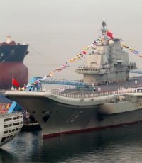
100 years after abandoning sailboats altogether, shipbuilders are turning to wind power again in an attempt to reduce fuel costs.
Here are a few transport ship projects that use alternative sources to deliver cargo.
Eco Marine Power - solar panels work like sails

The Japanese company Eco Marine Power (EMP) decided to create both a sailing and high-tech vessel at the same time, replacing traditional sails with .
EMP is an innovative company that applies new technologies to the design and construction of marine vessels. The company's engineers and researchers have set themselves the goal of developing more environmentally friendly engines for marine and river transport, in order to reduce both traditional energy sources and the harm caused by their use to the environment.
Instead of traditional sails, they used controlled solar panels. Firstly, their large area and the presence of a controlled rotating mechanism will allow the panels to be used as regular sails. And secondly, accumulated during the voyage Electric Energy will be used to power the engines when maneuvering the ship in port.
The rotating system of each solar panel allows you to position it perfectly in the wind or remove it completely in bad weather. When folded horizontally, the solar panels will still have their active surfaces facing sunlight and will additionally charge the on-board batteries.
EMP representatives claim that the rigidity and reliability of the design of their high-tech sails can withstand even very strong storms at sea, and therefore the ship will remain afloat and move on the approved course even when conventional sailing ships cannot. In addition, new sails require minimal maintenance.
EMP engineers have calculated that equipping a conventional ship with such unique sails will reduce fuel consumption by 20%, and if the ship is also equipped with additional electric motors, then the consumption will be reduced by almost half - by about 40%.