Complete transformer substation KTP: production, installation. Modern transformer substations KTP: production. Types of transformer stations
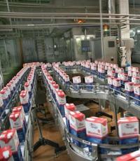
Complete transformer substations are used both in industrial enterprises and in public utility networks of populated areas. Their main advantage is considered to be operational reliability and relative low cost. KTPs cost two and sometimes three times less than conventional transformer stations. This electrical equipment is produced using a special technology with strict adherence to the standards stipulated by GOSTs. Therefore, if necessary, such a substation can be selected for absolutely any line.
Types of package transformer substations
Based on the location of installation, complete transformer substations are classified into KTP and KTPN. Blocks of the first type are installed indoors. Such substations are usually used in production. KTPN are more often used in utility networks. The dimensions of both types of substation may be different. A foundation is laid for large installations.
A KTP substation can have different capacities and purposes. On this basis, such equipment is divided into the following categories:
KTP with transformers with power from 25 to 400 kW. Such stations are installed outside.
KTP for industrial enterprises. This option is equipped with transformers with power from 160 to 250 kW.
Prefabricated package transformer substations.
Special purpose package transformer substations. Such structures can be used in mines, construction sites, quarries, etc. Their design includes an element such as a sled for movement.
Based on the assembly method, stations of this type are divided into mast-mounted, ground-mounted and built-in. The first type is installed on vertical supports. Ground stations can be assembled in metal, concrete or sandwich buildings.

Factories for the production of package transformer substations
The manufacture of PTS substations is carried out at enterprises whose structure includes:
Metalworking shop.
Assembly shop.
Low and medium voltage workshop. There is a tire processing, electrical installation, adjustment and testing area here.
Main design elements of a package transformer substation
The KTP substation is assembled in production using the following main elements:
high voltage input devices;
distribution cabinet for voltage removal.
The substation housing, depending on the purpose and design group, can be made of metal, concrete or sandwich blocks.

Modern transformer substations KTP: production
The manufacture of equipment of this type includes several main stages. The assembly of the most popular package transformer substations in a steel casing begins in the metalworking shop. The highest quality material is used for their manufacture. Body parts are usually made on special machines by bending and stamping. The workpieces obtained in this way are first treated with special anti-corrosion compounds. Then they are painted. In this case, powder products are usually used. Such dyes are the most resistant to negative factors environment.
The production of KTP substations continues in the assembly shop. Here, using the riveting method, all the blanks are connected into a finished body. Finally, all elements of the latter are installed in the medium and low voltage workshop. Here, in the tire processing area, elements of the tire system are manufactured using a special technology. Next, all the necessary communication equipment is installed in the housing. This operation is carried out at the electrical installation site. Then all automation and relay protection are assembled.
At the final stage, the finished station arrives at the commissioning area. Here it is checked for operability and compliance with the standards provided by GOST.

Production of stations in concrete shell
Complete transformer substations of this type are manufactured using a different technology. In this case, at the first stage, special molding installations are used. They are necessary for pouring the concrete shell of the substation. In the manufacture of the latter, frame reinforcement of the appropriate design is used. The hardened concrete block with technological holes is treated with special means that increase its resistance to adverse environmental factors. The cable floor of the resulting building is waterproofed.
Electrical equipment inside the unit is installed in the same workshop. It comes from the low and medium voltage section. After its installation, as in the first case, the equipment is tested and adjusted.
Installation of package transformer substations
Installation of stations of this type is usually carried out by specialists from the same company where they were manufactured. The site is carefully prepared before installation. Next, markings are made for the base of the station - foundation or support channels. A small KTP substation can be delivered to the installation site already assembled. Large equipment of this type is transported in parts - in blocks. They are assembled at the installation site.

After the foundation has been erected, the actual installation of the station begins. The cabinets are lifted using a truck crane. In the absence of such equipment, use special rollers made of thick steel pipes. To lift switchgears, inverter slings are used, attached to the ends of the support channels.
After the KTP substation is installed on the base, they begin to connect the electrical equipment. This stage consists of operations such as connecting transformer leads to the switchgear, assembling overhead and cable lines, etc.
After completion of this work, the reliability of all mechanical interlocks, devices and devices must be checked. The insulation is also carefully inspected to identify possible damage.
Installation of complete transformer substations KTP from several blocks
In this case, the installation is carried out using approximately the same method. However, when installing package transformer substations consisting of several main parts, among other things, the order in which the blocks are assembled must be observed. The last one is installed first. Next, the blocks are installed one by one. Before lifting, remove the plugs from each of them that cover the outward ends of the tires. After installing the blocks, the tires are welded to the support channels.
Features of connecting to the network
The KTP substation can have a radial or main power supply circuit. In the first case, when connecting according to the block-line-transformer principle, it is allowed to use a blind connection to the TM. If the power supply circuit of the station is mainline, a UVN cabinet is pre-installed. When the transformer power is 1000-1200 kW, 2-3 transformer substations are usually connected to one main line. If this figure is less, 3-4 stations are used.

Rules to follow
The installation of a KTP substation must be carried out in compliance with the following standards:
The station can be installed at an altitude of no more than 1000 m above sea level.
The ambient temperature must comply with the standards specified for this particular model. This parameter is indicated in the instructions (usually from -40 to +40 degrees).
There should be no explosive or chemically active substances in the immediate vicinity of the station.
Installed equipment should not be subject to shock, shock or vibration.
Features of operation
The main equipment that requires periodic maintenance in a substation is the equipment and the power transformer itself. When operating the PTS, the following standards must be observed:
The load current should not exceed the values specified in the instructions. In a station with two transformers, for example, it should not be higher than 80% of the nominal value.
Periodic monitoring of normal oil circulation through the filter is necessary. The check is performed by the degree of heating of the upper part of the casing.
Oxide film and sludge from the contact system should be removed at least once a year.

If everything is observed during the manufacture, installation and maintenance of the substation, it will continue to work uninterruptedly and for a long time. Otherwise you have management company or manufacturing enterprise All sorts of problems are bound to arise. Therefore, you should choose a package transformer transformer manufacturer carefully, focusing primarily on the reputation of the companies offering such services.
The production company "GOST Energo" offers to buy KTPN - a complete transformer substation with a capacity from 100 to 630 kVA of kiosk type, installation of a dead-end type module is carried out externally, there is the possibility of overhead or cable KTPN-TV/TK with 6 (10) kV input
Short description
- The substation housing is made of galvanized sheet steel 0.2 cm thick. The foundation of this electrical installation is a welded structure made of bent metal channel 0.3 cm thick. The color of the base is black. PF-115 was used for staining.
- The KTPn substation is equipped with metal partitions 0.2-0.3 mm thick. They are located between all three compartments of the electrical installation. The floor is made of a metal sheet 0.3 cm thick with a slope towards the hole for receiving oil.
- In accordance with the requirements of the electrical installation rules, a 1x1 cm mesh was installed in the ventilation grilles.
- All openings are equipped with cable clamps and rubber seals.
- Door locks have lugs for removable locks.
- This substation model is equipped with the most common, simple and economical TN-C grounding subsystem. Its main difference is the fact that a neutral conductor is used as a protective grounding conductor. The separation of wires is carried out only in the area where the consumer is connected to the electrical network. Bolts are used to connect metal elements, and copper conductors are used to connect moving parts.
- In the section of the 6-10 kV high voltage switchgear there is a single-sided maintenance chamber of the 300 series. It is equipped with the ability to install load switches, disconnectors and high-voltage fuses. KSO 300 is designed for distribution of 3-phase alternating current electricity.
- The 0.4 kV low voltage switchgear provides the possibility of installing 8 outgoing lines with auto switches and 4 lines with circuit breakers of the RPTs series.
- In the transformer section it is possible to install 3-phase oil transformers for converting electricity in power system networks.
Equipment
- 3 pcs. Surge suppressors
- 1 PC. KTPn substation
- 1 PC. Transformer compartment barrier.
- 6 m. AD31 bus for connecting TM.
- 1 set Set of hardware
- 1 PC. Passport
- 1 PC. User manual
Specifications
- Rated voltage, 6(10) kV
- Highest operating voltage, 7(12) kV
- Nominal frequency, 50 Hz
- Climatic modification and placement category according to GOST 15150, UHL1
- Weight (Net) of KTPn-TV excluding power transformer, up to 950 kg
- Weight (Net) KTPn-TK excluding power transformer, up to 1150 kg
- Overall dimensions (transportation) of KTPn-TV (H x W x D), 2200 x 1700 x 1700 mm.
- Overall dimensions (transportation) of KTPn-TK (H x W x D), 2200 x 1700 x 2820 mm.
- The following files will be available for download in the near future:
- Declaration of conformity KTPn 630 U1
- Operating manual KTPn 630 U1
- Questionnaire KTPn 630 U1
- Standard design KTPn 630 U1
- Example of Estimate for installation of KTPn 630 U1
- Test report KTPn 630 U1
- Executive document. KTPn 630 U1
Photos


Description
The equipment is intended for use in power supply systems of enterprises operating in the energy sector, oil and gas production, as well as in the gas and chemical industries. This electrical installation is also used to supply electricity to construction sites and urban infrastructure facilities. These models can be equipped with the possibility of cable or air voltage input.
KTPn are divided into the following types: one- and two-transformer, dead-end and through. Our complete transformer substations fully meet all requirements state standards And technical specifications operation. In accordance with the characteristics of the climatic design, they can be used outdoors in temperate climates.
The warranty period is three years from the date of commissioning of the power unit. The warranty is not valid if more than three and a half years have passed since shipment from the KTPn manufacturer. The estimated service life of this electrical equipment is 25 years.
Operating conditions of the KTP
- installation at altitudes up to 1000 m;
- operation in the range from -45 to +40°C;
- Application is possible only in a non-explosive environment in which the content of conductive dust, destructive vapors and gases is reduced to zero.
- The degree of electrical safety corresponds to class IP31 (protection against foreign bodies over 2.5 cm in size and vertically falling drops).
Structure symbol
| _ | KTPn | GE | T | TO | TO | 630 | 10 | 0,4 | UHL1 |
|---|---|---|---|---|---|---|---|---|---|
| 1 | 2 | 3 | 4 | 5 | 6 | 7 | 8 | 9 | 10 |
1 — Number of power transformers (indicated only for a two-transformer substation);
2 - Complete transformer substation for outdoor installation;
3 — Trademark Rated voltage, kV;
4 - Design: T - dead-end, P - walk-through;
5 - Execution of the HV output: V - air, K - cable;
6 - LV output design: B - air, K - cable;
7 - Power transformer kVA;
8 - Rated voltage on the HV side - 6; 10 kV;
9 - Rated voltage on the LV side - 0.4 kV;
10 — Climatic modification and placement category UHL1 according to GOST 15150-69;
An example of recording the symbol of a single-transformer complete transformer substation of a dead-end kiosk type KTPn with a power of 630 kVA, rated voltage on the HV side - 10 kV, rated voltage on the LV side - 0.4 kV, s cable entry HV and LV cable outlet, climatic version UHL1:
Complete transformer substation KTPn-GE-T-KK-630/10/0.4 /UHL1
Technical characteristics of KTP
|
Substation type |
HV side |
LV side |
||||||||||
|
Rated current, A. |
||||||||||||
|
Transformer |
Fuse link |
Transformator |
Feeder street Lighting |
Electricity metering |
||||||||
|
KTP-XX-100/6/0.4 |
||||||||||||
|
KTP-XX-100/10/0.4 |
||||||||||||
|
KTP-XX-160/6/0.4 |
||||||||||||
|
KTP-XX-160/10/0.4 |
||||||||||||
|
KTP-XX-250/6/0.4 |
||||||||||||
|
KTP-XX-250/10/0.4 |
||||||||||||
|
KTP-XX-400/6/0.4 |
||||||||||||
|
KTP-XX-400/10/0.4 |
||||||||||||
|
KTP-XX-630/6/0.4 |
||||||||||||
|
KTP-XX-630/10/0.4 |
||||||||||||
Note:
- At the customer's request, changes in the number and rated currents of circuit breakers for outgoing lines are allowed (no more than 8 pcs.)
- If, according to the customer’s declared configuration, the sum of the rated current values of the linear circuit breakers exceeds the specified value for the standard configuration, the manufacturer declines responsibility for possible overload of power equipment during operation of the substation.
Dimensions and weight
|
Substation type |
Length, no more, mm |
Width, no more, mm |
Height, no more, mm |
| KTP-VV-100…630-6(10)/0.4 | |||
| KTP-KK-100…630-6(10)/0.4 | |||
| KTP-VV-1000-6(10)/0.4 | |||
| KTP-KK-1000-6(10)/0.4 | |||
| 2KTP-VV-630…1000-6(10)/0.4 | |||
| 2KTP-KK-630…1000-6(10)/0.4 | |||
| KTPP-VV-630…1000-6(10)/0.4 | |||
| KTPP-VV-630…1000-6(10)/0.4 |
KTP design
The body is made of galvanized sheet steel 0.2 cm thick. At the customer’s request, it can be painted with a 2-component primer-enamel with an anti-corrosion effect. For painting, paintwork materials based on acrylic resins are used. This paint is different high level resistance to negative influences of the external environment.
Transformer substations of this type are equipped with:
- High voltage switchgear;
- section for power plants;
- Low voltage switchgear.
Insulation is installed between all sections.
Customers have the opportunity to additionally equip the KTPn with an outdoor disconnector, which is mounted on a power line support located as close as possible to the given electrical installation.
The high voltage switchgear is equipped with the following equipment:
- high-voltage input chambers, which are equipped with load switches, non-linear voltage limiters, disconnectors and fuses.
- high voltage cables. In electrical installations that have cable input/output, there are openings for the entry of such cables. They are located at the base of the high voltage switchgear section. Special towers are used for air input/output.
- devices for conducting and insulating live parts and high-voltage arresters (optional), which are installed on the roof of the tower.
Transformer section
The design features of the KTPn module suggest the possibility of replacing or 2-way maintenance of the power electrical installation. The doors of the transformer section are equipped with louvered grilles, which are used for natural ventilation and cooling of the installed equipment. Substations with a power of 400-630 kVA can be additionally equipped with forced ventilation or directly with a power unit. This ensures optimal temperature.
A low voltage switchgear, made in the form of a shield, can be equipped with the following equipment:
- auto switches;
- control panel designed to monitor electricity consumption and current voltage level;
- an automatic device designed to turn on street lighting;
- low voltage arresters.
The design of a transformer substation of this type provides for the possibility of forced blocking:
- grounding and main knives. This interlock prevents the grounding knives from being put into operation if the main knives are already in operation.
- drive of grounding knives. This feature prevents the risk of the door opening when the grounding blades are not working.
Cable transformer substations of this type provide for the possibility of transportation exclusively in assembled form. Aerial KTPN can be transported not complete with aerial towers. They can be transported separately (like the traverse). It is worth adding that power transformer units are also transported separately. For installation, specially prepared and pre-compacted areas of earth or concrete blocks, the height of which reaches 60 cm, are used.
Linear fittings and insulation of overhead lines
When installing PKU for the installation or reconstruction of an overhead line, I use crossbars, suspension fittings, and insulators.
Although, in fact, all the diversity of energy production and consumption can be reduced to such a diagram, many people are no longer interested in looking at it (especially for electricians), because very important things are ignored. But what is important is what is vitally relevant, that is, in some ways useful, and in some ways even potentially dangerous.
Principle of operation
This is our energy industry as a whole and its many components, which do not immediately fit into the everyday consumer and necessarily philistine worldview.
And what we see every day, although it seems habitually cozy and safe, its other “end” necessarily leads to things that are even scary to touch in the imagination.
This is what the modern power grid is all about.
Of course, only one complete link is presented here, but it contains all the necessary parts:
- Electricity generation subsystem;
- Electricity transmission subsystem;
- Electricity distribution subsystem;
- Consumption subsystem.
In reality, now the energy system of any state and even any independent economic territory - a province, a republic, a district - is a numerous repetition of this scheme and the connection of them all into a powerful network in which continuous processes of energy flow take place from places where more of it is produced to those where more energy is generated. where the demand has increased at this time, and it is not covered by locally located energy sources.
That is, the most important feature of modern energy systems is the need for continuous transportation of electricity over long distances. In our country, such distances are calculated in thousands of kilometers.

In such an energy system, one cannot even call the highways “power lines”; these are entire rivers along which energy flows of unimaginable power flow.
To transmit energy over long distances, they strive to reduce its losses, which, in general, are inevitable, but depend on the voltage through which the energy is transmitted. The larger it is, the lower the heating losses in the wires. Therefore, they strive to increase the voltage in electrical lines.

To the places where energy is consumed, it is reduced step by step, and three-phase 380 volts, or, roughly speaking, 0.4 kV, is supplied to the end consumer. For ordinary household consumers, as a rule, one phase is allocated from three phases, and in it the voltage changes 50 times per second from zero to 220 volts. Transformers are used to transform energy flowing through the power grid in any direction and for different purposes.
But these transformers are not just two coils on a w-shaped core, which are found in each household appliance. This is a whole enterprise that must work reliably and safely, dealing with gigantic currents and voltages.
That’s why this whole facility is called an electrical or transformer (TS) substation.

The last step in the multi-stage transfer of energy to our household network is carried out by a whole “swarm” of transformer substations, which lower the penultimate two voltage levels to a household voltage of 0.4 kW. Since their tasks are, in general, the same, their design is very compact so that they can be installed in close proximity to the consumer in different conditions - natural, geographical, demographic.
Explanation of abbreviations
These transformer substations are called “complete transformer substations,” the abbreviation KTP.
Completeness in KTP means that an entire substation is produced for outdoor use and outdoor installation in the form of kits, which consist of the transformer itself (this includes all its electrics), its oil cooling system, assemblies for its floor, walls and roof, as well as everything necessary racks for measuring instruments. Based on the QFT decoding, there are other options. For example, KTPB. The beginning of the contraction is the same, and the B stands for block. And KTPN are complete transformer substations for outdoor installation. This is a transformer substation, manufactured as a kit, but also as a block, that is, delivered to the installation site immediately assembled.
KTP can be deciphered as an abbreviation for complete transformer substations, which are used so that the current of a high-voltage network can be changed.
Traditionally, such structures are made in the form of a metal case with a transformer located inside, providing from 25 to 4 thousand kW of power. The neutral of such substations is grounded. They can be used virtually everywhere - at small industrial facilities, in various residential areas, in agriculture enterprises, in construction.
The key advantages of these facilities are reliable operation and relatively low cost. The price of a package transformer substation is twice, and sometimes even three times lower than that of substations made from transformers. These power supply objects are produced using a special method under conditions of strict compliance with the standards regulated by GOSTs. As a result, if necessary, this equipment can be customized to suit completely different requirements.
Types of package transformer substations
TS (transformer substations) are divided according to their location into external and internal locations. The internal installation equipment is located in a permanent building. Traditionally, this type of substations is used at production facilities. Outdoor electrical substations are increasingly used in urban communications. Their sizes can be varied. Foundations are poured for particularly bulky equipment.
The capacities and uses of PTS are very diverse. According to this indicator, these electrical installations are divided into the following options:
Based on their structural elements, stations of this type are divided into mast-mounted, ground-based and integrated. The first ones are located on vertical pillars. Ground-mounted substations are equipped with metal, reinforced concrete buildings or blocks made of sandwich panels.
General characteristics
KTP are traditionally used in power supply complexes for consumers’ own needs, manufacturing companies, as well as mines and mines. If we take into account two-component substations, then we must take into account that they have a sectional module that includes two inputs, including from a diesel power plant (diesel power plant).
The environment must meet the following requirements:
- Explosion proof.
- It should not contain vapors and gases that are hostile to insulating materials.
- Electrically conductive dust must be absent.
Device
The usual configuration of power supply devices consists of 3 components. All of them are located in a metal body, a welded body made of sheets and profiles. It contains a HVN (high voltage device), a low voltage switchgear switchgear and the transformer itself.
To carry out maintenance, electricians enter the premises through swing gates. All electrical connections are made using bus connections or flexible connections. The KTP also includes a device for external inclusions and other components that support the necessary parameters.
External transformer points, unlike KTPM (mast substations), have a much wider range of capacities. This makes it possible to use external complete devices in a wide range of applications, and there are also samples with 25-4 thousand kilovolt-ampere characteristics.
 The normal operation of the KTPN is determined by the organization of installation work prescribed by special standards. The manufacturer has the opportunity to deliver the device to the site of operation either block-by-block or completely assembled. On the front side there is an assembly diagram.
Transport elements ready for installation work. There is no need to disassemble the switching equipment. The reliability of hidden connections is checked before assembly begins. Assembly components are equipped with special devices for the use of lifting mechanisms when moving and lifting. The assembled substation is placed on a flat surface. Before use, tests of all electrical substation complexes are organized.
Completeness
The range of devices and systems for installing a CTP pump is varied. Most used components:

The list of tools used is adjusted according to the customer’s wishes..
Types of transformer stations
Now in production a large number of various complete devices. Substations of the first type are connected to only one power line. They are called dead ends. Substations of the second type have connections to two power lines. These are walk-through transformer substations. The third, most frequently used ones are kiosk electrical substations.
Explanation of the abbreviation KTP:
K - complete
T - transformer
P -- substation
- Decoding of KTPN: installation type is added - external.
- Decoding BKTP-block.
- Explanation of other types of package transformer substations in electrical engineering:
 KTPM - mast
KTPSH - cabinet
KTPS - pillar
KTPP - mobile
VKTP - in-shop
KTPNU - external installation
KTPVU - indoor installation
KTPTAS - dead-end
KTPPAS - checkpoint
KTPB - block
KChTP - frequency
KTPSN - auxiliary substation
KTPK - kiosk type. KTP TAS, KTP PAS kiosk type assume one or two transformer substations of external installation and operate to receive electrical energy current frequency 50 Hz with a voltage of 6 or 10 kV, its transit (pass-through substations) and transformation into electricity with a voltage of 0.4 kV. As well as power supply and consumer protection for populated areas, industrial and other facilities in areas with different temperatures (from minus 45 to plus 40 degrees).
Decoding of the symbolic designation of KTP TAS, KTP PSA
X KTP X X X X
X - 2 - two-transformer
KTP - complete transformer substation
X - T - dead-end; P - pass-through
X - SA - stationary switch 0.4 kV
X - M - modernized
X - transformer power, kVA
Technical regulations
Electrical substations receive, distribute and convert alternating electric current.
Technical standards of KTP:

KTPN cannot be used:
In case of vibration, pulsation, shock and explosive factors,
To receive power on the 0.4 kV side,
Application Specifics
Key devices, which require regular repairs in electrical substations, is considered to be the equipment of distribution boards and, in fact, the electrical transformer itself. When using CTP, the following rules should be followed:

Installation of a PTS installation in production consists of the following key elements:
- high voltage input device;
- oil or dry power transformer;
- distribution cabinet for voltage removal.
During the production, assembly and service of the electrical substation, comply with technical regulations, uninterrupted and long work guaranteed. Otherwise, the user may encounter operational problems. As a result, select a manufacturer of package transformer substations must be done very carefully, focusing first on the reputation of the companies offering such services.
 KTP substation connection diagrams can be radial or main. Radial, connected according to the block - power line - electric transformer circuit, are connected tightly. At the main line, an UVN shield is additionally installed. Connecting several package transformer substations to one line is possible with their power of 1000-1200 kVA.
If a KTPN is connected, then the cables are connected using a KNTP-terminal coupling for outdoor installation.
Block complete transformer substations (BCTS) are used to receive, convert and distribute electrical energy of three-phase alternating current of industrial frequency and are intended for use in power supply systems of urban housing and communal, public and industrial facilities, as well as individual development zones and cottage villages
MAIN TECHNICAL CHARACTERISTICS:
|
Parameter name |
Meaning |
|
Power transformer power. kVA |
25; 40; 63; 100; 160; 250; 400; 630; 1000; 1250; 1600 |
|
Rated voltage on the HV side, kV |
6;10;20 |
|
Rated voltage on the LV side, kV | |
|
Rated current of busbars on the HV side, A | |
|
Rated current of busbars on the LV side, A |
1250;1600;2500;3200 |
|
Thermal resistance current of busbars on the HV side, kA/1s |
16;20 |
|
Climatic design according to GOST 15150 |
U1 (at ambient temperatures below -25°C, BKTP are manufactured in a northern version) |
|
Degree of protection according to GOST 14254 |
IP23 |
|
Seismicity of the construction area, points on the MSK-64 scale |
Up to 9 |
|
Altitude above sea level, m |
Up to 3000 |
|
Service life, years |
At least 25 |
2BKTP modules can be arranged either “sequentially” - joining along the width of the block, or “parallel” - joining along the length of the block. The latter relative arrangement is the most common.
M - mass with installed equipment, without transformer, S - perimeter area,
H internal - internal height of the element.
DESIGN CHARACTERISTICS OF BKTP
|
Element |
Dimensions, mm (WxDxH) |
M, t |
S.m2 |
Internal, mm |
|
Dimensions of one TP block |
2460x4640x2700 |
12.7 |
11,5 |
2175 |
|
2460x4640x3050 |
13.5 |
11,5 |
2475 |
|
|
2460x5340x3050 |
13.1 |
2475 |
||
|
Dimensions of the volumetric pit (underground part of the transformer substation) |
2380x4560x885 |
11.0 | ||
|
2380x4560x1500 |
11.0 |
1415 |
||
|
2380x5260x1500 |
12.5 |
1415 |
Equipment of serial BKTP.
High voltage switchgear (RU-VN).
Small switchgear switchgear type R.M. -6 with gas insulation (produced by EZOIS under license Schneider Electric).
At the customer's request, SF6 monoblocks of other types (manufactured by ABB, Siemens ). It is also possible to perform RU-VN on the basis of KSO cells from Russian manufacturers. The possibility of using cells of the proposed type must be agreed with EZOIS. Available own production equipment 6-10 kVA.
Power transformer.
BKTP standard designs are equipped with power transformers ( 25; 40; 63; 100; 160; 250; 400; 630; 1000; 1250; 1600) with oil-cooled sealed type (TMG) from various manufacturers. At the customer's request, cast resin transformers can also be used various types and manufacturers.
Low voltage switchgear (RU-LV).
BCTS are made using 0.4 kV switchgear of various designs (racks, panels, cabinets) with switching and protective devices of various types (load switches, fuses, circuit breakers) and from different manufacturers. We have our own production of 0.4 kVA equipment.
Automatic transfer system (ATS).
To ensure the required degree of reliability of power supply to consumers, package transformer substations produced by the plant can be equipped with devices for automatically switching on backup power.
ATS in standard package transformer substations can be carried out on the HV side (AVR-VN) or on the LV side (AVR-LV). In both options, the ATS circuit operates in the following emergency situations:
· violation of the phase sequence;
· loss of voltage on one, two or three phases (decrease below the permissible level (0.7*Unom) on any of the phases or on all three).
Scheme with AVR-VN is implemented by equipping the drives of the RU-VN switching devices with geared motors and contacts for signaling the position of the devices. The switching control is carried out by an automation cabinet, which monitors the presence of voltage on the LV side.
Scheme with AVR-NN implemented either on contactors or on motor-driven circuit breakers. The AVR-NN device is a set of two identical panels (cabinets), each of which is installed in the room of the corresponding section (circuit beam) of the package substation. AVR-NN can be built into RU-NN when automatic switches are used as input and sectional devices.
Reactive power compensation devices (RPC).
Depending on the design parameters of the operating mode distribution network low voltage, PTS can be equipped with reactive power compensation devices.
UKRM can be either the type specified by the project or selected according to design parameters (power, number of control stages). Structurally, the UKRM can be made as a separate device or be built into the RU-NN.
If the substation contains UKRM, the layout of the package transformer substation may differ from the standard one and is developed individually.
System of own needs (lighting, heating, heating of equipment).
The auxiliary system (SN) provides power for lighting and space heating, ventilation systems, forced heat removal (if available), and equipment heating. The auxiliary circuit provides manual or automatic power backup in the presence of two sources (in two-transformer transformer substations). If the balance of the premises is different (of the power supply company and the subscriber), the circuit allows for independent switching on of power to its parts.
Lighting system substations includes equipment for working and emergency lighting (lamps, batteries, automation devices) of the unit, as well as equipment for lighting the pit (in standard version- sockets for connecting a portable lamp).
Heating KTP blocks are carried out due to the heat generated power transformer. For the northern version (or at the customer’s request), electric heaters with a control device (regulator with air temperature sensor) are installed in the RU-NN and RU-VN rooms. Anti-condensation heating of equipment (compartments of relay protection and automation equipment RU-VN, gearmotors of drives of switching devices) is provided regardless of the regional design of the package substation.
Electricity measurements and metering.
Measurement electrical quantities (current and voltage) in serial PTS are carried out on the low voltage side, at the input to the RU-NN. Measuring instruments are located in the auxiliary power supply cabinet (YASN or ShPSN). It is also possible to place measuring instruments in RU-NN. At the customer's request, various types of measuring instruments can be used.
Electricity metering also carried out on the low voltage side. If necessary, electricity metering can be performed both at the input and output lines of the RU-NN. In addition, RU-NN can be manufactured with preparation for metering electricity on outgoing lines (with wiring for metering circuits, but without installing current transformers).
Alarm systems.
At the customer's request, the KTP can be equipped with security and fire alarm systems. They are carried out according to standard projects and include a full set of equipment (sensors, control equipment and warning devices).
Telemechanics system.
The equipment of the transformer substation can be prepared in preparation for equipping it with a telemechanics system. To carry out telemetering, telesignaling and telecontrol in this case, standard package transformer transformer equipment is equipped with additional options:
· contacts for signaling the position of switching devices RU-VN and RU-NN;
· contacts for signaling the position of switching devices of the MV system;
· gearmotors and releases for remote control devices;
· sensors of electrical quantities (current and voltage transformers).
In addition, fire and security alarm systems are designed with the ability to transmit signals to the telemechanics system.
At the customer's request, the list of signals transmitted to the telemechanics system and functions for remote control of equipment can be expanded in accordance with the provided project.
The telemechanics system can be supplied as a complete set with the package transformer substation, or purchased separately and installed by the customer independently at the site.
BKTP sales at the best price are carried out through all over Russia.
In Moscow, you can find out the price of buying a BKTP at the head office at: