Submarine deck superstructure. Fire weapons of German submarines. Dive and ascent system
Submarines of the Shch type, or, as they were also called, pikes, occupy a special place in the history of domestic shipbuilding. These were the most numerous (86 units!) medium submarines Soviet fleet period of the Great Patriotic War. They actively participated in hostilities in the Baltic, Black Sea, and Arctic; their torpedoes and artillery sank a German submarine, a patrol ship, two landing craft and at least 30 enemy transports. But the price of victory turned out to be extremely high: 31 “pike” did not return to their home base and remained at sea forever. Moreover, the circumstances of the death of many submarines are unknown to this day...
However, let’s dwell on the history of the service submarines we will not. We offer exclusive material - reconstruction appearance"pike" of all six series: III, V, V-bis, V-6hc-2, X and X-bis. The developed drawings are based on original documentation from the funds of the Central Naval Museum (TsVMM), the Russian State Archive navy(RGAVMF), as well as special literature and numerous photographs.
Despite the fact that all series of boats of the “Shch” type were quite similar in their characteristics, in appearance they differed significantly from each other. Thus, the first four submarines Shch-301 - Shch-304 (III series) had a straight stem, a narrow superstructure and a wheelhouse fence, in the aft part of which there were gratings for blowing ventilation shafts. The bow horizontal rudders were of a unique design - they “horned” in the front part into special slots in the hull. The bow gun originally had a bulwark, but immediately after testing it was removed, and the wheelhouse fence itself was completely rebuilt. For the convenience of the crew of the 45-mm gun, folding semicircular platforms were installed, and later, during the overhaul, these platforms became permanent and were equipped with a tubular railing.
On series V submarines built for the Pacific Fleet, the shape of the bow rudders was changed (it became standard for all subsequent pike series) and the width of the superstructure was increased. The wheelhouse fence was radically reconstructed, placing a second 45-mm gun on it. The stem became inclined, and its contours in the upper part formed a small “bulb”. The length of the light hull has increased by 1.5 m.
The submarines of the V-bis series differed from their predecessors only in the shape of the false keel and the fencing of the wheelhouse (the latter lost a kind of “balcony” above the first gun). But on the V-6nc-2 series, the contours of the light hull were changed and the wheelhouse fence was again redone. Moreover, Pacific boats of this type differed from the Baltic and Black Sea ones in the shape of the sides of the navigation bridge.
The X series submarines looked the most exotic due to the introduction of a streamlined wheelhouse fencing of the so-called “limousine” type. Otherwise, they were practically no different from the V-bis-2 series ships, with the exception, perhaps, of the “hump” that appeared above the deck tank and diesel mufflers.
Since the expected increase in speed underwater in the X series boats did not occur, and the flooding of the navigation bridge increased, the last series of X-bis pikes used a more traditional wheelhouse fencing, reminiscent of that designed for C-type submarines. The bow 45-mm cannon was now installed directly on the deck of the superstructure. The hull remained unchanged, but the underwater anchor disappeared from its equipment.
The racks of antennas and network outlets on boats of the III, V and V-bis series were L-shaped and connected by crossbars. The net drain cables ran from bow to stern; in front of the bow strut they were combined into one.
In the “pike” \/-bis-2 and X series, the power outlet racks became single; on the X-bis series they were absent altogether. Some of the boats were equipped with “Som” and “Crab” net cutters, which were a system of cutters (four on the stem, two on the forecastle linearly elevated and one on each side), as well as a system of guy ropes that protected the protruding parts of the boat from getting caught by net fence cables. In practice, these devices turned out to be ineffective, and they were gradually dismantled, covering the saw on the stem with metal sheets.
The exhaust openings of the mufflers in the superstructure on the boats of the first four series were located on both sides, on the submarines of the X and X-bis series - on one, left side. Only on the left side was there an anchor, which was used in the surface position.
The location of scuppers in the superstructure, which is often an individual feature of the ship and therefore of particular interest to modellers, is, as a rule, not indicated on design drawings (since it is not of fundamental importance). In the proposed drawings of the pikes, the scuppers are drawn from photographs and therefore their location may not be entirely accurate (this especially applies to the Shch-108). It should also be borne in mind that the cutting of scuppers on boats of the same series often differed greatly; These differences are most clearly demonstrated by the Baltic and Black Sea “pikes” of the X series.
The appearance of the Shch type submarines also changed due to modernizations carried out during the service. Thus, the folding parts of the gun platforms were gradually replaced by permanent ones and equipped with railings. Based on the experience of sailing in broken ice and in fresh weather, the outer covers of the torpedo tubes were removed from some of the boats. Instead of a second gun, a DShK machine gun was sometimes installed, and the Pacific Fleet had homemade installations, along with a standard pedestal one. External 7.62-mm M-1 (Maxim) machine guns were not always placed in their standard places on the surface. The emitters of the underwater communication installation were located on the deck (upper) and in a special enclosure (lower). During the war, some pikes received Asdik sonars (Dragon -129) and a demagnetizing device with windings outside the hull at the level of the superstructure deck.
Coloring: the hull and superstructure of the Baltic boats above the waterline were gray-spherical, those of the Black Sea were dark gray, and those of the North Sea were gray-green. The underwater part is black (kuzbasslak) or coated with anti-fouling compounds No. 1 and 2 (dark red and dark green). IN besieged Leningrad In addition to camouflage nets, they used to paint the boats white to match the snow background. The screws are bronze. Rescue buoys were painted in the color of the hull; after the war they became red and white (three sectors of each color). The letters of the boat names in the bow (on III, V, V-bis, \/-bis-2 series) are brass. The letter-numeric designation on the wheelhouse is white (except for the V series, where it was yellow or blue with a black outline); during the war years they were painted over to match the main color of the body. The number of declared victories was indicated by a number in a circle located in the center of a red star with a white outline, drawn on each boat individually. The star was always placed in the bow of the cabin, approximately in the middle of the height or below the portholes.
Shch type submarines:
1 - rudder blade; 2- wave-cutting shields of torpedo tubes; 3.9 - wake lights; 4 bale strips; 5 - ducks; 6 - rescue buoys; 7,13,37 - racks of network outlets; 8- network outlet (combined with radio antenna); 10- gyrocompass repeaters; 11 - periscopes; 12 - magnetic compasses; 14 - radio direction finder antennas; 15 - 45 mm 21-K guns; 16 - mooring spiers; 17 - bollards; 18 - noise direction finder antennas; 19.35 - bow horizontal rudders; 20 - fender; 21 - wheelhouse hatches; 22 - emergency exit hatches; 23 hinged covers over the boats; 24 - folding superstructure grilles; 25 - aft horizontal rudders; 26 - folding gratings above the torpedo loading hatch; 27- stern flagpole; 28 muffler exhaust valves; 29 - retractable masts; 30 - anti-aircraft machine gun "Maxim"; 31,32 - running lights; 33 - guy rod; 34 - hatches above the fenders of 45 mm cartridges; 36 - anchor hawse (on all submarines - only on the left side); 38-V-shaped radio antenna post; 39 - bale strips with net outlets; 40- radio antenna; 41 - retractable davit; 42 lifting hook niches
|
Performance characteristics of "Shch" type submarines |
||||||
|
V bis |
||||||
|
Displacement normal, cubic meters |
||||||
|
Maximum length, m |
||||||
|
Maximum width, m |
||||||
|
Average draft (keel), m |
||||||
|
Diesel power, hp |
2x685 |
2x685 |
2x685 |
2x800 |
2x800 |
|
|
Electric motor power, hp |
2x400 |
2x400 |
2x400 |
2x400 |
2x400 |
|
|
Travel speed, knots: maximum. surface |
||||||
|
economy, surface |
||||||
|
most underwater |
||||||
|
savings, underwater |
||||||
|
Cruising range, miles: surface economic speed |
||||||
|
underwater in full swing |
||||||
|
economically underwater |
||||||
|
Crew, people |
||||||
|
Number of 533 mm torpedo tubes: bow |
||||||
|
feed |
||||||
|
Artillery armament: number of guns X x caliber in mm |
2x45 |
2x45 |
2x45 |
2x45 |
2x45 |
|
|
Number of boats built (years of entry into service) |
||||||
The outer lightweight hull of the submarine had the shape of a cylinder, gradually tapering towards the bow and stern. The main deck of the superstructure extended from the bow to frame 124 at the stern. In the bow it rose above the water level by 3.7 m, and in the stern by 1.2 m. The internal cavity between the superstructure and the strong hull was filled with water through scuppers during the dive.
The conning tower, located in the midship frame area, was covered from above by a bridge fence. The deck located immediately behind the wheelhouse was called the “cigarette deck” because sailors were allowed to smoke on it. A Browning anti-aircraft machine gun of 7.62 or 12.7 mm caliber was also installed here.
When submerged, the machine gun was retracted inside the boat. In 1941, machine guns were replaced by 20-mm Oerlikon Mark 4 Mod anti-aircraft guns. 3 with a rate of fire of 450 rounds/min, and in 1944 the Gato began to be equipped with 40 mm Bofors cannons with a rate of fire of 160 rounds/min.
The deck in front of and behind the bridge had a reinforced structure for installing guns. The artillery armament of the Gato boats was very diverse. The type and location of the guns depended on the time the boat was commissioned and the wishes of its commander.
At first, two deck-mounted 76.2 mm guns were installed on the submarines, but they turned out to be very weak weapons and could not cause serious damage even to small ships. During the operation of the boats, these guns were replaced with more powerful 102 mm or 127 mm Mk40 guns.
Their projectiles had several times greater mass and initial flight speed. In addition, the barrels of the 127-mm guns were made of stainless steel, which made it possible not to close the barrel with a plug when diving, and this speeded up bringing the weapon into firing position after surfacing.
At the bottom of the wheelhouse enclosure there were lockers for ammunition.
There were many visual differences between submarines produced by different shipyards. Most noticeable were the number, location and configuration of the scuppers. Some submarines were equipped with additional weapons and equipment.
And it is not without reason that naval historians claim that it is impossible to find two absolutely identical boats of the Gato type.
Hydroacoustic equipment
The first series of boats were equipped with WCA type sonars with a JT hydrophone. The hydrophone operated in the range 110 Hz - 15 kHz. The sonar range was 3429 m. It made it possible to determine the bearing and range to the target, and if the target was a submarine, then the diving depth was also determined. In 1945, the more advanced WFA sonar was adopted.
Of interest is the analysis of submarine operations carried out by the Bureau of Research during and after the war. This institution, organized in Washington and located in Pearl Harbor, analyzed 4,873 submarine attacks. It turned out that only 31 of them were produced using sonar devices. Moreover, of these attacks, only seven ended in the sinking of enemy ships.
To determine the temperature of the sea water, a barothermo-graph was used - SVT40131. In addition, a Benedix hydrodynamic log was installed on the submarines.
Series VII submarines were easy-to-manufacture one-and-a-half-hull boats. The side bulges, bow and stern ends and deck superstructure were welded to the durable hull. The diameter of the pressure hull in the area of the central post was only 4.7 meters. The thickness was 16 mm at the ends 18.5 mm in the center, and together with the connections to the deckhouse it was 22 mm. On the C/41 modification, the thickness increased to 18.5 mm at the ends and to 21.5 mm in the central part.
The durable hull of these submarines could withstand not only the outboard water pressure, but also the fire of machine guns and small-caliber cannons of ships and aircraft. In post-war tests of captured boats, it turned out that 20, 23 mm shells and 37 mm incendiary fragmentation shells caused damage only to the light hull. Also, because of this, the Allies observed problems when trying to ram the submarine. There is a known case when an American destroyer Borie Having rammed the submarine, U-405 received severe damage and was sunk by its own aircraft.
The durable body was welded from eight sections, six of them were sheets of metal, bent and welded into cylinders. The bow and stern sections were welded from three sheets of metal. The sections were sequentially welded to each other, then the deckhouse was welded to them. A fairly large hole was left behind it, through which instruments and mechanisms were loaded into the boat.
The latest to be installed were diesel engines. After installing them, the hole was welded with a steel sheet. This made it clear that the boat was not designed for long-term operation; the destruction of the submarine was expected earlier than the time it was put on average for repairs. Type VII was divided into six compartments. The central post was separated from the concavity side by spherical bulkheads designed for a pressure of 10 atm; it could serve as a shelter compartment.
Placement of instruments and mechanisms in the compartments:
1st compartment (bow torpedo)
This compartment housed four torpedo tubes. two in vertical rows and a supply of six torpedoes. Four were stored under the deck deck and two along the side. For loading and loading torpedoes, the boat had special internal transport and loading devices. Also, along each side there were three pairs of folding, two-tier bunks. At the bottom of the compartment, under the spare torpedoes, there were bow trim and torpedo replacement tanks, as well as a manual control drive for the bow horizontal rudders.
2nd compartment (bow accommodation)
The compartment was divided into two parts by a thin bulkhead and a door. The room located closer to the bow was small; it housed a latrine and places for four sergeants. Next came the officer's quarters with two bunks in two tiers on each side. At the bulkhead of the central post, on the left side there was a captain's berth, separated from the aisle by a curtain. Since it was very small, the only furniture it contained was the bed itself, a folding table, a cabinet built into the wall.
On the starboard side of the boat, opposite the captain’s seat, there were sonar and radio operator posts. Under the deck flooring there was a bow battery group (consisting of 62 elements), air cylinders high pressure and an artillery cellar.
3rd compartment (central post)
The anti-aircraft periscope was located here, the commander's was located higher in the conning tower. Also, control posts for kingston valves and ventilation, drives remote control horizontal rudders. Here was the navigator's combat post. The largest mechanisms in this compartment are two pumps and a hydraulic motor that raised the periscopes.
Along the sides there were tanks with drinking water and hydraulic oil. An equal-strength ballast tank of large volume was located under the central post, it played the role middle group. Fuel tanks are located on both sides of it. Above the central post, in the narrow conning tower, there was the commander’s combat position during a torpedo attack - a folding seat (rotated along with the commander’s periscope), a PSA (counting and solving device) for controlling torpedo firing.
4th compartment (aft accommodation)
In the jargon of submariners it was called "Potsdamer Platz" because of the prevailing noise, din and running around, since this compartment connected the galley, diesel and electric motor compartments with each other. Also in the compartment there were beds for four non-commissioned officers, a second latrine and a second power station. Under the deck flooring there was a second group of batteries, high-pressure air cylinders and a fuel tank.
5th compartment (diesel)
Almost the entire compartment above the deck flooring was occupied by two huge diesel engines. Also here, there were cylinders with compressed air for starting engines and a cylinder with carbon dioxide for extinguishing fires. At the bottom of the compartment under the diesel engines there were oil tanks.
6th compartment (electric motor and stern torpedo)
The compartment housed two high-pressure air compressors, diesel on the starboard side, electric on the left. There were two electric motors, a stern torpedo tube, power and manual control posts for horizontal rudders. Under the deck flooring, between the electric motors, there was a spare torpedo; closer to the stern, there was a trim and torpedo replacement tank. There was a hatch in the roof of the compartment for loading torpedoes. At the end of the war, a device similar to a torpedo tube, but inferior in size, appeared in the compartment; it was intended for the release of imitation Bold cartridges.
Superstructure
Inside the light hull and superstructure there were systems and mechanisms, the most important of which were hydrophones, a capstan device, an anchor, four waterproof cases for inflatable rafts, camouflage nets, two cases for storing spare torpedoes (one case was closer to the bow, the other closer to the stern , they could store G7a torpedoes). There were waterproof fenders for the first shots for the 88 mm deck gun, an air supply shaft for the diesel engines, exhaust valves and diesel mufflers, and most of the high-pressure air system cylinders.
The superstructure deck was made of wooden planks, since wood froze later than iron. The deckhouse fence was used to accommodate anti-aircraft guns, numerous movable and fixed devices, as well as for watchkeeping. Behind, inside the fence, there was an air intake for the air supply shaft to diesel engines and fenders for the first shots for anti-aircraft guns.
Dive and ascent system
The main ballast of the boat consisted of five tanks. The first and fifth tanks were located in a light hull, the fifth tank was in the bow, there was also a quick submersion tank, and the first tank was located in the aft end, the second and fourth tanks were in the side bulges, the third tank was in the durable hull of the 3rd compartment. All tanks, except the first and third, could be filled with fuel.
In addition to the middle group, the main ballast tanks were kingless, and the valve control was located at the central station of the boat. Between the second and fourth tanks, there were two small fuel and ballast tanks, a surge tank and an onboard buoyancy tank. The VVD system was assembled from steel pipes and was not designed for long-term use.
The total volume of VVD cylinders is 3.46 m³, since 1944 the volume has been 5.2 m³. The compressed air was under a pressure of 295 kg/cm². To replenish compressed air supplies there were two 6-liter compressors - diesel and electric. Two pumps were part of the drainage and trim systems, with a capacity of 30 and 18 tons, respectively.
At a signal, the top watch personnel jumped into the wheelhouse and battened down the hatch, the watchmen of the central post shifted the horizontal rudders to dive and opened the ventilation valves of the main ballast tanks from bow to stern. The well-thought-out shape of the horizontal rudders allowed German boats to dive with a large trim on the bow and not be afraid to make a somersault.
To speed up the dive, “live” ballast was used; the entire crew of the boat, free from watch duty, had to run to the bow compartment. These actions were practiced both during the introductory combat training course and during combat campaigns. Within 25-27 seconds, a trained crew could take the boat to a depth of 10 meters.
Power plant
The power plant of the Type VII submarines consisted of two six-cylinder four-stroke diesel engines F46, which were installed on most boats, or MAH M6V 40/46 engines with mechanical supercharging. Engine power on modifications A was 1169 hp, on all other modifications 1400 hp. Maximum speed the speed on diesel engines was 16.9 knots; when running on diesel engines with electric motors, the speed was 17.4 knots.
In the summer of 1943, due to Allied aviation, German submarine operations in the Atlantic were stopped. In February 1944, after repairs, U-264, the first German Type VII submarine equipped with a snorkel, entered service. The snorkel itself consisted of the following: two pipelines from the diesel compartment were connected in the bow of the wheelhouse to a special folding mast; at the end of this mast there was a valve for air intake and exhaust gas release from diesel engines. The design of the valve provided for its automatic closing when water entered, but the diesel engines did not stop and took air from the internal compartments of the boat, this could create a large vacuum in a closed environment.
Despite the difficulties in operation, the snorkel was a device thanks to which the boat, in a submerged position, fully charged its battery in three hours at a speed of 3-4 knots. Every 20 minutes, the underwater passage using a snorkel and diesel engine was stopped and a hydroacoustic search was carried out.
Typically, electric motors were used to move underwater. The Type VII boats had two twin-anchor electric motors from the company Siemens , A.G. or Brown Boweri with a power of 375 hp As on Soviet submarines, electric motors and diesel engines were connected to the propeller shaft by mechanical couplings. Battery 124 cells types 27-MAK 800, later 33-MAL 800W. The ventilation of the elements is individual, the flooring of the pits is hermetic.
The normal supply of fuel in the internal tanks was 62.14 tons, the total supply in the fuel and fuel-ballast tanks was 105.3 tons, when the surge tank was filled with fuel, it was 113.47 tons. The supply of fresh water on board the boat was 3.8 tons, oil 6 tons, and oxygen - 50 liters. The endurance of Type VII submarines is approximately 40 days. The cruising range at a speed of 10 knots is 8500 miles; with diesel-electric transmission, the range increases to 9700 miles. The diving range depended on the type of batteries, 130 miles at 2 knots or 80 miles at 4 knots.
Longitudinal elements (beams) vessel are:
- keel- longitudinal beam of the bottom frame, running along the middle of the width of the vessel;
- stringers- longitudinal beams of the bottom and side frame. Depending on their location, they are: side, bottom and zygomatic.
- Carlings- longitudinal under-deck beams;
Longitudinal stiffeners - longitudinal beams of a smaller profile than those of stringers and carlings. Based on their location, they are called below-deck, side or bottom and provide rigidity to the outer skin and deck flooring during longitudinal bending.
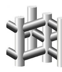
Transverse elements of the vessel
Transverse elements (beams) of the vessel:
- Floras are transverse beams of the bottom set, stretching from side to side. They are waterproof, solid and bracketed;
- Frames are vertical beams of the side frame, which are connected below to the floors using brackets. A bracket is a piece of triangular-shaped sheet steel used to connect various parts of the body. On small vessels (boats), flora may be absent and the frames are solid beams of the side and bottom frames.
- Beams are transverse beams of a deck set, running from side to side. If there are cutouts in the deck, the beams are cut and called half beams. They are connected at one end to the frame, and at the other they are attached to a massive coaming, which borders the cutout in the deck, in order to compensate for the weakening of the deck floor with cutouts.
On rice. 1 shows the simplest structure of the hull of a small boat, indicating the main elements of the set, and on rice. 2 a more complete set of wooden motor boat hulls is presented.
Rice. 1. Structure of the hull of a small vessel.
1 - stem; 2 - keel; 3 - stringer; 4 - side trim; 5 - transom; 6 - frame; 7 - beam; 8 - deck
The ship's frames are numbered from bow to stern. The distance between the frames is called spacing. Vertical, free-standing racks of round or other cross-section are called pillars.

Rice. 2. Elements of a wooden motor boat hull kit.
1 - casing; 2 - deck; 3 - beam; 4 - frame; 5 - seats; 6 - transom; 7 - motor mounting location;
8 - side stringer; 9 - fender; 10 - zygomatic stringer; 11 - keel; 12 - bottom stringers
The pillars serve to reinforce the deck and in its lower part rests on the intersection of the floors (frames - on small ships) with the bottom longitudinal beams (keel, stringer, keelson), and in the upper part - beams with carlings. Piller installation is shown in rice. 3.

Rice. 3. Piller installation
1 - deck flooring; 2 - carlings; 3 - beam; 4 - transverse coaming; 5 - pillers;
6 - second bottom flooring; 7 - flor; 8 - keel; 9 - bottom trim.
Vertical or inclined beams that are a continuation of the keel are called stems (in the bow - stem, in the stern - stern). The ship's hull can be divided into separate compartments using transverse and longitudinal watertight bulkheads. The bow of the ship between the stem and the first bulkhead is called the forepeak, and the aft compartment is the afterpeak. U motor boats a waterproof structure at the transom that forms a niche and is designed to accommodate a boat motor is called a motor niche. The motor niche, located above the water level and equipped with scuppers - holes for draining water, is called a recess niche.
For a more complete picture of the elements of the body kit, see rice. 4 shows a cross-section of a dry cargo ship with a combined recruitment system, and Fig. 5th set of metal boat hull "Chibis".

Rice. 4. Combined dialing system.
1 - gunwale; 2 - bulwark stand; 3 - bulwark; 4, 10-beams; 5 - deck flooring; 6 - carlings; 7 - stiffener; 8 - hatch coaming;
9 - pillers; 11 - bulkhead pillar; 12 - transverse bulkhead; 13 - second bottom flooring; 14 - keel; 15 - horizontal keel; 16 - bottom stringer;
17 - bottom trim; 18 - flor; 19 - outer double-bottom sheet; 20 - zygomatic keel; 21 - zygomatic belt; 22, 25 - frame;
23 - half beam; 24 - side trim; 26 - knitsa; 27 - shearstrek.

Rice. 5. Boat hull set.
1 - frame frame; 2 - carlings; 3 - coaming; 4 - deck flooring; 5 - fender; 6 - frame; 7 - side trim;
8 - zygomatic square; 9 - flor; 10 - stringer; 11 - keel; 12 - bracket; 13 - bottom plating; 14 - knitsa.
External cladding
The outer plating of the vessel ensures the waterproofness of the hull and at the same time participates in ensuring the longitudinal and local strength of the vessel. On metal ships, the hull consists of steel sheets placed with the long side along the ship. In addition to steel sheets, especially on metal motor boats and boats, sheets of aluminum alloys are used. Sheathing sheets are connected using rivets and butt welding. A series of planking sheets running along the ship is called a belt. The upper belt of the side skin is called shirstrvkom, and below there are side belts and on the cheekbone - the zygomatic belt. The middle bottom belt is called the horizontal keel. The line of connection of one belt with another is called a groove, and the place where the sheets join each other in one belt is called a joint. The sizes of sheets and their thickness are different and depend on the design of the vessel, its size and purpose. For the cladding of boats, motor, sailing and rowing boats, wood materials, laminated plastics, fiberglass, textolites and other materials that meet the requirements of shipbuilding in their properties and strength are very often used.
Deck flooring
The deck flooring ensures the watertightness of the hull from above and is involved in ensuring the longitudinal and local strength of the vessel. The greatest load during longitudinal bending falls on the deck in the middle part of the ship, so the deck sheets at the end are somewhat thinner than in the midship area. The flooring sheets are located with the long side along the ship, parallel to the centerline plane, and the outermost chords of the left and right sides are located along the sides; they are called deck stringers and are thick. The deck stringer is connected to the shearstrak by riveting, welding or gluing, depending on the material of the decking sheets.
Hatches and necks
Hatches and necks weaken the strength of the deck; stress concentrations arise in their corners, contributing to the appearance of cracks. In this regard, the corners of all cutouts in the hull plating are rounded, and the deck sheets at the corners of the cutouts are made more durable. To strengthen the deck, weakened by the cutouts, and to prevent water from entering the hatch, a coaming is made along the edges of the cutout, which has a device for closing the hatch (neck). The coaming also borders the cutouts in the bulkheads; the coaming is also called the part of the bulkhead under the doorway.
Bulwark and railing
On sea, river and modern pleasure boats, to protect people from falling overboard, open decks have a bulwark or railing.
Bulwark(rice. 6) is, as a rule, a metal belt of the side plating. It is installed on low decks prone to flooding in stormy weather.

Rice. 6. Bulwark.
1 - buttress; 2 - bulwark; 3 - gunwale; 4 - stiffening strut.
On the inside, the bulwark is supported by racks, which are called buttresses and are installed through two or three spacing. To increase the strength of the bulwark, ribs are sometimes welded between its posts. Along the upper edge of the bulwark, a strip is strengthened, which is called a gunwale. To drain water overboard that falls on the deck, cutouts are made in the bulwarks - storm porticoes. Considering that the complete removal of water through the storm ports is prevented by the deck stringer angle, then for complete drainage of water from the deck overboard, scuppers are made - cutouts in the edge of the shearstrake protruding above the deck and in the deck stringer angle. Railing fencing (rice. 7) consists of vertical posts connected to each other by tightly stretched cables (rails) or chains.

Rice. 7. Guardrail (removable).
The racks can be connected to each other by two, three or four rows of horizontal round rods, most often steel. These horizontal rods are called rails.
Shipbuilding materials
There are basic materials used for the manufacture of hulls, kit elements, ship devices and parts.
Steel- has many properties necessary for building a ship (density 7.8 g/cm3). It is durable and easy to process. The most commonly used shipbuilding steels are carbon and low-alloy steels.
Sheet steel has a thickness from 0.5 to 4 mm (thin sheet) and 4 - 1400 mm. In shipbuilding, the most common sheets are 6-8 m long and 1.5-2 m wide. From carbon steels They produce profiles: corner, channel, I-beam, strip-bulb and z-beam, and from low-alloy steels the same profiles, except z-beam and I-beam. Sheet steel is used to make hull plating, bulkheads, second bottom, decks, etc.; from the profile: beams, frames, stringers and other elements of the hull. The casting method produces parts of complex shapes: anchor fairleads, anchors, chains, stems, propeller brackets, etc.
Aluminum alloys have a lower density than steel (2.7 g/cm3) and sufficient strength. The most common are alloys of aluminum with magnesium and manganese. These alloys are used to make small vessels, superstructures, partitions, pipelines, ventilation pipes, masts, ladders and other important ship parts.
Wood and wood materials for many years (until the 19th century) they were the only material for building ships. Having many advantages, wood continues to be used in shipbuilding today. The hulls of small sea and river vessels, boats, dinghies, rowing boats, sports and sailing ships, deck coverings, decoration for ship premises, etc. are made from wood. Pine is most often used in shipbuilding. It is used to make kits and plating. Spruce is used for lining the underwater part of the vessel, because it is less hygroscopic. Larch and teak are used for decking and external cladding, for finishing residential and office premises- oak, beech, ash, walnut, birch and others. In addition, the stems of wooden ships are made from beech and ash, incl. undersized. Beams, boards, slats, plywood and wood slabs are widely used in shipbuilding, used for the manufacture of external cladding of ships, finishing of cabins, salons, etc.
Plastics Due to low density, good dielectric and thermal insulation properties, high corrosion resistance, convenient processing methods and sufficient strength, they increase the service life of individual ship parts. erasers are divided into two main groups: thermoplastics (plexiglass, nylon, polyethylene and other plastics that can again acquire a plastic state when heated and harden when cooled) and thermosets - plastics that cannot be re-softened when heated, i.e. plasticity. The most widely used in shipbuilding are fiberglass plastics - various synthetic resins (epoxy, polyester, etc.) reinforced with fiberglass in the form of fabric, mats, strands. Fiberglass is used to make small vessels (boats, boats, yachts, boats), pipes and other ship structures and parts.
The main disadvantages of plastics are: low heat resistance, low thermal conductivity, tendency to plastic deformation under the influence of constant load at normal temperature (creep).
Cast iron used for the manufacture of cast products: bollards, bale strips, stern tubes, propellers and other parts.
Bronze- an alloy of copper with tin or aluminum, manganese, iron. Sliding bearings and linings are made from it propeller shafts, Kingston housings, worm wheels and other parts.
Brass- an alloy of copper and zinc. Pipes for heat exchangers, porthole parts, electrical parts, propellers and other products are made from it.
Reinforced concrete- a material consisting of concrete reinforced with a metal frame. It is mainly used for the construction of floating docks, cranes, and landing stages.
Superstructures and deckhouses
Superstructures are all enclosed spaces located above the upper deck from side to side. The bow superstructure is called the forecastle, the stern superstructure is called the poop. The middle superstructure has no special name. A superstructure having a width less than the width of the vessel is called a deckhouse. For example, the chart room. The design of decks and sides of superstructures and deckhouses is similar to the design of other decks and sides on ships. The side plating and bulkheads of superstructures, as a rule, are thinner and may differ in material from the hull.
In this note, I bring to your attention the firepower that the boats had. I again reviewed the topic briefly, without providing details and nuances, since a detailed coverage of this issue would require writing at least a large review article. To begin with, to make it clear how the Germans highlighted the issue of the need to have a gun on board and its use, I will give an excerpt from the “Manual for Submarine Commanders”, where the following is said about this:
"Section V Artillery weapons of submarines (submarine as a carrier of artillery)
271. The presence of artillery on a submarine is fraught with contradictions from the very beginning. The submarine is unstable, has a low-lying gun and surveillance platform, and is not equipped to conduct artillery fire.
All artillery installations on a submarine are poorly suited for an artillery duel, and in this respect the submarine is inferior to any surface ship.
In an artillery battle, a submarine, as opposed to a surface ship, must immediately bring all its forces into action, because even one hit in the strong hull of a submarine already makes it impossible for it to dive and leads to death. Therefore, the possibility of an artillery battle between a torpedo submarine and military surface ships is excluded.
272. For submarines used for torpedo attacks, artillery is, as it were, a conditional and auxiliary weapon, because the use of artillery over water contradicts the entire essence of a submarine, i.e., a sudden and covert underwater attack.
Based on this, it can be said that on a torpedo submarine, artillery is used only in the fight against merchant ships, for example, to delay steamships or to destroy unarmed or weakly armed ships (§ 305)."(With)
Deck artillery
Caliber, Type, Shooting, Rate of fire, Elevation angle , Effect. range, Calculation
105 mm SK C/32U - U-boot L C/32U Single 15 35° 12,000 m 6 persons
105 mm SK C/32U - Marine Pivot L Single 15 30° 12,000 m 6 persons
88 mm SK C/30U - U-boot L C/30U Single 15-18 30° 11,000 m 6 people
88 mm SK C/35 - U-boot L C/35U Single 15-18 30° 11,000 m 6 people
Of all types of German submarines designed and built from 1930 to 1945, boats of the I, VII, IX and X series were armed with deck artillery with a caliber of over 88 mm. At the same time, only the VII series carried an 88-mm caliber gun; the rest of the indicated series of boats had a 105-mm gun. The cannon was located directly on the upper deck in front of the wheelhouse; the ammunition was stored partly there in the superstructure of the boat, partly inside the durable hull. Deck artillery was in the department of the second watch officer, who performed the duties of a senior gunner on the boat.
On the "sevens" the gun was installed in the area of frame 54 on a pyramid specially reinforced in the superstructure, which was reinforced with longitudinal and transverse beams. In the area of the gun, the upper deck was expanded to 3.8 meters in length, thereby forming a place for artillery crews. The standard ammunition for the boat was 205 shells - 28 of which were in special containers in the superstructure next to the gun, 20 shells in the wheelhouse, and the rest in the "weapons room" inside the durable hull in the second compartment from the bow.
The 105 mm gun was also mounted on a pyramid, which was welded to the pressure hull. Depending on the type of boat, the ammunition for the gun ranged from 200 to 230 shells, of which 30-32 were stored in the superstructure next to the gun, remaining in the “weapons room” located in the central control room and galley.
The deck gun was protected from water by a waterproof plug on the barrel side, and by a special plug sleeve on the breech side. A well-thought-out lubrication system for the gun made it possible to keep the gun in working condition at different temperatures.
I mentioned various cases of using deck guns
And .
By the end of 1942, the command of the submarine forces came to the conclusion that the deck guns on boats that participated in the fighting in the Atlantic theater of operations should be dismantled. Thus, almost all “sevens” of type B and C lost such artillery. The guns were retained on Type IX submarine cruisers and Type VIID and X mines. But by the end of the war it was already difficult to find a German boat of any type that could carry deck artillery.
88 mm U29 and U95 guns. The waterproof plug is clearly visible.

Elevation angle of the 88 mm gun on the U46. It seems that it still exceeds those 30 and 35 degrees indicated in the technical characteristics. The gun had to be raised with its barrel up when loading torpedoes into the bow compartment. The photo below shows how this happened (U74 preparing to take a torpedo) 

105 mm gun on the U26 "one" 
105 mm guns U103 and U106 

General view of the 105 mm gun with its mounts. 
Gunners U53 and U35 prepare for practical shooting 

Artillery crew U123 is preparing to open fire. A tanker is visible straight ahead. The target will be sunk by artillery fire. Completion of Operation Paukenschlag, February 1942. 
But sometimes the tools were used for other purposes :-)
The pictures below show U107 and U156 

Flak
Caliber, Type, Shooting, Rate of fire, Elevation angle , Effect. range, Calculation
37 mm SK C/30U - Ubts. LC 39 Singles 12 85° 2,500 m 3/4 persons
37 mm M42 U - LM 43U Automatic (8 rounds) 40 80° 2,500 m 3/4 persons
37 mm Zwilling M 42U - LM 42 Automatic (8 charges) 80 80° 2,500 m 3/4 persons
30 mm Flak M 44 - LM 44 Automatic (exact characteristics unknown. For type XXI submarines)
20 mm MG C/30 - L 30 Automatic (20 rounds) 120 90° 1,500 m 2/4 persons
20 mm MG C/30 - L 30/37 Automatic (20 rounds) 120 90° 1,500 m 2/4 persons
20 mm Flak C/38 - L 30/37 Automatic (20 rounds) 220 90° 1,500 m 2/4 persons
20 mm Flak Zwilling C/38 II - M 43U Automatic (20 rounds) 440 90° 1,500 m 2/4 persons
20 mm Flak Vierling C38/43 - M 43U Automatic (20 rounds) 880 90° 1,500 m 2/4 persons
13.2 mm Breda 1931 Automatic (30 rounds) 400 85° 1,000 m 2/4 persons
Quad units are highlighted in red, dual units are highlighted in blue.
Of the fire weapons that the German submarines had, the most interesting were anti-aircraft weapons. If deck guns were obsolete by the end of the war, then the evolution of anti-aircraft fire among the Germans is clearly visible from the above table.
By the beginning of the war, German submarines had only a minimum of anti-aircraft guns, since it was believed that the threat from the air was clearly underestimated by the fleet command. As a result, the designers in the projects included no more than one anti-aircraft gun on the boat. But during the war the situation changed and reached the point that some submarines were literally studded with anti-aircraft guns, such as “anti-aircraft boats” (flakboats).
The main weapons of the boats were initially recognized as 20-mm 20-round anti-aircraft guns, which were installed on all types of boats with the exception of the II series. On the latter they were also provided, but were not included in the standard armament of the boats.
Initially, on the first "sevens" in pre-war times, a 20-mm anti-aircraft machine gun of the MG C/30 - L 30 type was supposed to be installed on the upper deck behind the wheelhouse. This is clearly seen in the example of U49. Behind the open hatch you can see the anti-aircraft gun carriage. 
But already in wartime, the 20-mm anti-aircraft gun was moved to a site located behind the bridge. It is clearly visible in the photo. Alternately, anti-aircraft platforms U25, U38 (Karl Doenitz himself is on the bridge of the boat), U46 


Depending on the type and purpose of the boat, "Dvoyki" received anti-aircraft weapons, both pre-war and during the war. The gun was located in front of the wheelhouse. Either a carriage was installed for it, or it was installed there on a waterproof container (in the form of a barrel) in which the machine gun was stored in a disassembled state).
U23 before the war 
Waterproof "barrel", also known as a carriage on U9 (Black Sea) 
Same thing on U145 
And this is already in finished form. U24 (Black Sea) 
Option for installing an anti-aircraft gun on a carriage. U23 (Black Sea) 
The "Twos" operating in the Black Sea underwent some modification. In particular, the wheelhouse was modified in the direction of standard ocean boats by adding a platform for installing additional fire weapons. Due to this, the armament of boats of this type at the World Theater Championship increased to 2-3 guns per submarine. The photo shows U19 in full armor. Anti-aircraft gun in front of the wheelhouse, twin guns on the platform behind the bridge. By the way, machine guns installed on the sides of the cabin are visible.  The growing threat from the air forced the Germans to take measures to increase anti-aircraft weapons. The boat received an additional platform for placing fire weapons, on which two pairs of 20-mm machine guns and one (or two) 37-mm machine guns could be placed. This site received the nickname "Winter Garden" (Wintergarten). Below are photos of boats that surrendered to the Allies U249, U621 and U234

As the pinnacle of the evolution of anti-aircraft weapons on German boats, the quad anti-aircraft gun Flak Vierling C38/43 - M 43U, which was received by the so-called “anti-aircraft boats”. As an example U441.
In the Mediterranean, the "Sevens" received additional weapons by installing Italian "Breda" machine guns in the form of twin-arms. As an example U81 
A special word worth mentioning is such a “miracle” weapon as the 37 mm SK C/30U - Ubts anti-aircraft gun. LC 39, which fired single shots. This gun was installed on later types submarine cruisers Type IX (B and C) and Type XIV submarine tankers. The "cash cows" carried two guns of this type on either side of the wheelhouse. "Nines" had one installed behind the wheelhouse. Below are examples of such a weapon on the U103. 

Since I did not set myself the task of conducting a complete and detailed description anti-aircraft weapons, I omit such nuances as ammunition and other characteristics of this type of weapon. I once mentioned the training of anti-aircraft gunners on submarines. Examples of confrontation between submarines and aircraft can be found if you look at the topics in my tag.
Firearms and signal weapons
Caliber, Type, Shooting, Rate of fire, Elevation angle , Effect. range, Calculation
7.92 mm MG15 Automatic (50/75 rounds) 800-900 90° 750 m 1-2
7.92 mm MG34 Automatic (50/75 rounds) 600-700 90° 750 m 1-2
7.92 mm MG81Z Automatic (Tape) 2.200 90° 750 m 1-2
In addition, the submarine’s crew had at their disposal 5-10 Mauser 7.65 mm pistols, 5-10 rifles, MP-40 assault rifles, hand grenades and two flare guns.
MG81Z on U33 
In general, I would like to note that German submarines had fire weapons that were quite modern at that time, which worked well during combat operations. In particular, the British noted after testing the artillery they captured U570 that, compared with the 3-inch gun of the 1917 model mounted on S-type boats, the 88-mm German gun was superior to the British one. The 20-mm anti-aircraft machine gun was recognized by them as an excellent and effective weapon, which, to their surprise, did not vibrate when fired and had a good magazine.
Photo resource used to illustrate the note http://www.subsim.com
As usual, Vladimir Nagirnyak pored over the analysis.