Download presentation on diodes. Presentation "Electron-hole transition. Transistor" presentation for a physics lesson (grade 10) on the topic. Types of devices and their designations
Chapter 2 Semiconductor DiodesSemiconductor
diode
is
yourself
semiconductor device with one p-n junction and two
conclusions. Most diodes are based on
asymmetrical p-n junctions. At the same time, one of the areas
diode, usually (p+) highly doped and called an emitter,
other
(n)
lightly alloyed
–
base.
P-n junction
placed in the base because it is lightly alloyed.
Structure, symbol and the name of the conclusions
shown in Fig. 3.1. Between each outer area
semiconductor and its output there is an ohmic contact,
which in Fig. 3.1 is shown with a bold line.
Depending on the manufacturing technology, there are:
point diodes, alloy and microalloy, with diffusion
base, epitaxial, etc.
By
functional
purpose
diodes
divided:
rectifier, universal, pulse, zener diodes and
stabistors, varicaps, tunnel and reversed, as well as microwave diodes, etc.
Classification of diodes by functional purpose and their UGO
2.1. Current-voltage characteristic of the diode
The current-voltage characteristic of a real diode has a number of differences from the current-voltage characteristic of a p-n junction (Fig. 3.2).For forward bias, volumetric resistance must be taken into account
areas of the base rb and emitter rе of the diode (Fig. 3.3.), usually rb >> rе. A fall
the voltage across the volume resistance from the diode current becomes
significant at currents exceeding several milliamps. Besides,
part of the voltage drops across the terminal resistance. As a result
the voltage directly at the p-n junction will be less than the voltage,
applied to the external terminals of the diode. This leads to a displacement of the line
branches of the current-voltage characteristic to the right (curve 2) and an almost linear dependence on the applied
voltage.
The current-voltage characteristic of the diode, taking into account the volume resistance, is written by the expression
φU
I I 0 e T 1
Uφ Irb
I I 0 e T 1
where Upr is the voltage applied to the terminals; r is the total base resistance and
diode electrodes, usually r=rb.
When the diode is reverse biased, the diode current does not remain constant equal to I0
those. an increase in reverse current is observed.
This is explained by the fact that the reverse current of the diode consists of three components:
Iobr =I0 + Itr + Iut
U φ Irb
T
I I0 e
1
where I0 is the thermal current of the transition;
Itr – thermal generation current. It increases with increasing reverse voltage.
This is due to the fact that p-n junction expands, its volume increases and
consequently, the number of minority carriers produced increases
in it due to thermal generation. It is 4-5 orders of magnitude greater than the current I0.
Iut – leakage current. It is related to the finite value of surface conductivity
crystal from which the diode is made. In modern diodes it is always
less thermal current.
Semiconductor diodes
A semiconductor diode is an electrical converting semiconductora device with one electrical junction and two terminals, which uses
various p-n properties- transition (one-sided conductivity, electrical breakdown,
tunnel effect, el. capacity).
Rectifier diode
Germanium diode Silicon diode
Zener diode
Varicap
Tunnel diode
Reversed diode
2.2. Diode equivalent circuit
This is a circuit consisting of electrical elements that take into accountphysical processes occurring in the p-n junction and the influence
structural elements for electrical properties.
Equivalent circuit p-n substitutions transition at small
signals, when the nonlinear properties of the diode can be ignored
shown in Fig. .
Here CD is the total capacitance of the diode, depending on the mode; Rп = Rdiff
- differential transition resistance, the value of which
determined using the static current-voltage characteristic of the diode at a given operating
points (Rdiff = U/ I|U=const); rb - distributed electrical
resistance of the diode base, its electrodes and terminals, Rth –
leakage resistance.
Sometimes the equivalent circuit is supplemented with capacitance between the terminals
diode SV, capacitances Svh and Svyh (shown in dotted lines) and
inductance of the terminals LV.
The equivalent circuit for large signals is similar
previous one. However, it takes into account the nonlinear properties of the p-n junction by replacing the differential resistance with
source dependent current source I = I0(eU/ T – 1).
2.3. The influence of temperature on the diode's current-voltage characteristic
I0(T)=I(To)2(T-To)/T*,Temperature environment has a significant impact on
current-voltage characteristic of the diode. With temperature changes slightly
the course of both the forward and reverse branches of the current-voltage characteristic changes.
As the temperature increases, the concentration of non-basic substances increases
carriers in a semiconductor crystal. This leads to an increase in reverse current
transition (due to an increase in the current of its two components: Iо and Itr), as well as
reducing the volumetric resistance of the base area. When increasing
temperature, the reverse saturation current increases approximately 2 times at
germanium and 2.5 times for silicon diodes for every 10 °C. Addiction
reverse current versus temperature is approximated by the expression
I0(T)=I(To)2(T-To)/T*,
where: I(T0)-current is measured at temperature T0; T – current temperature; T*
- reverse current doubling temperature - (5-6) 0С – for Ge and (9-10) 0С – for Si.
The maximum permissible increase in the diode reverse current determines
maximum permissible temperature diode, which is 80-100 °C
for germanium diodes and 150 - 200 °C for silicon diodes..
Leakage current depends weakly on temperature, but can significantly
change over time. Therefore, it mainly determines the time
instability of the reverse branch of the current-voltage characteristic.
As the temperature increases, the direct branch of the current-voltage characteristic shifts to the left and
becomes steeper (Fig. 3.3). This is explained by the growth of Irev (3.2) and
by decreasing rb, the latter reduces the voltage drop at the base, and
the voltage directly at the junction increases at a constant voltage
on external pins.
To assess the temperature instability of the direct branch, we introduce
temperature coefficient of voltage (TKN) t = U/ T, showing
how does the forward voltage on the diode change with a change in temperature by
10C at fixed forward current. In the temperature range from -60 to
+60 "С t -2.3 mV/°С.
2.4. Rectifier diodes
Rectifier diodes - designed to rectify low-frequencyAC current and are commonly used in power supplies. Under straightening
understand the transformation of bipolar current into unipolar current. For straightening
The main property of diodes is used - their one-way conductivity.
As rectifier diodes in power supplies to rectify large
currents using planar diodes. They have a large contact area p and n areas
and a large barrier capacitance (capacitance Xc=1/(ωC), which does not allow
rectify at high frequencies. In addition, such diodes have a large value
reverse current.
The main parameters characterizing rectifier diodes are
are (Figure 2.1):
- maximum forward current Ipr max;
- voltage drop across the diode at a given value of forward current Ipr (Upr
0.3...0.7 V for germanium diodes and Upr 0.8...1.2 V for silicon diodes);
- maximum permissible constant reverse voltage of the diode Urev max;
- reverse current Irev at a given reverse voltage Urev (value
the reverse current of germanium diodes is two to three orders of magnitude greater than that of
silicon);
- barrier capacitance of the diode when reverse voltage is applied to it
of some size;
- Fmax - frequency range in which the diode can operate without significant
reducing rectified current;
- operating temperature range (germanium diodes operate in the range 60...+70°C, silicon diodes - in the range -60...+150°C, which is explained by small
reverse currents of silicon diodes).
Average power dissipation of the diode Рср Д – average power over the period
dissipated by the diode when current flows in the forward and reverse directions.
Exceeding the maximum permissible values leads to a sharp reduction in the period
service or diode breakdown.
By improving cooling conditions (ventilation, use of radiators), it is possible
increase power output and avoid thermal breakdown. Application of radiators
It also allows you to increase the forward current. Single Phase Half Wave Rectifier
Single phase full wave
mid point rectifier
Industry
are issued
silicon
rectifier diodes for currents up to hundreds of amperes and reverse
voltages up to thousands of volts. If it is necessary to work at
reverse voltages exceeding the permissible Urev for
one diode, then the diodes are connected in series. For
increase
straightened
current
Can
apply
parallel connection of diodes.
1) Half-wave rectifier. Transformer
serves to reduce the amplitude of alternating voltage.
The diode is used to rectify alternating current.
2) Full-wave rectifier. Previous diagram
has a significant drawback. It consists in the fact that it is not
part of the energy of the primary power source is used
(negative half-cycle). The deficiency is eliminated in
full-wave rectifier circuit.
In the first positive (+) half-cycle, current
proceeds like this: +, VD3, RH↓, VD2, - .
In the second – negative (-) like this: +, VD4, RH↓ , VD1,- .
In both cases he
flows through the load in one
direction ↓ - from top to bottom, i.e. straightening occurs
current
Single phase bridge rectifier
2.5. Pulse diodes
Pulse diodes are diodes that are designed to operate in switching mode in pulse circuits. Diodes inIn such circuits they act as electrical switches. The electric key has two states:
1. Closed when its resistance is zero Rvd =0.
2. Open when its resistance is infinite Rvd=∞.
Diodes satisfy these requirements depending on the polarity of the applied voltage. They have little
resistance when biased in the forward direction, and high resistance when biased in the opposite direction.
1. An important parameter of switching diodes is their switching speed. Factors
limiting the diode switching speed are:
a) diode capacitance.
b) the rate of diffusion and the associated time of accumulation and resorption of minority charge carriers.
In pulse diodes high speed switching is achieved by reducing the pn junction area, which reduces
diode capacitance value. However, this reduces the maximum forward current of the diode (Idirect max.). Pulse
diodes are characterized by the same parameters as rectifiers, but also have specific ones associated with
switching speed. These include: Time to establish the forward voltage on the diode (tset): tset. –
time during which the voltage on the diode, when the forward current is turned on, reaches its stationary value with
specified accuracy. This time is associated with the rate of diffusion and consists of a decrease in the resistance of the base area over
due to the accumulation of minority charge carriers injected by the emitter. Initially it is high, because small
charge carrier concentration. After applying forward voltage, the concentration of minority charge carriers in the base
increases, this reduces the forward resistance of the diode. Diode Reverse Resistance Recovery Time
(trecovery): defined as the time during which the diode reverse current after switching
polarity of the applied voltage from direct to reverse reaches its stationary value with a given
accuracy. This time is associated with the resorption from the base of minority charge carriers accumulated during the flow
direct current. trestore – time during which the reverse current through the diode when switching it reaches its
stationary value, with a given accuracy I0, usually 10% of the maximum reverse current. trestore= t1.+ t2. , Where
t1. – resorption time during which the concentration of minority charge carriers at the pn junction boundary turns to
zero, t2. – time of discharge of the diffusion capacitance, associated with the resorption of minority charges in the volume of the diode base. IN
In general, recovery time is the time it takes to turn off the diode, like a switch.
2.7. Zener diodes and stabilizers
A zener diode is a semiconductor diode made from weaklydoped silicon, which is used to stabilize constant
voltage. The current-voltage characteristic of a zener diode with reverse bias has a section of small
dependence of voltage on current flowing through it. This area appears behind
calculation of electrical breakdown (Fig. 1.5).
The zener diode is characterized by the following parameters:
Rated stabilization voltage Ust. nom - rated voltage
on a zener diode in operating mode (at a given stabilization current);
rated stabilization current Ist.nom – current through the zener diode at
rated stabilization voltage;
minimum stabilization current Ist min - lowest current value
stabilization, in which the breakdown mode is stable;
maximum permissible stabilization current Ist max - highest current
stabilization, in which the heating of the zener diodes does not exceed permissible limits.
Differential resistance
Rst - voltage increment ratio
stabilization to the stabilization current increment that causes it: Rst =
TKN – temperature coefficient of stabilization voltage:
TKN
Ust / Ist.
U st.nom.
100%
U st.nom. T
– relative change in voltage on the zener diode reduced to one
degree.
Ust.nom.< 5В – при туннельном пробое.
Ust.nom. > 5V – during an avalanche breakdown.
The parameters of zener diodes also include the maximum permissible forward current
Imax, maximum permissible pulse current Ipr. and max, maximum permissible
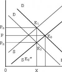
dissipated power P max. Parametric voltage stabilizer (Fig. 9.). It serves to provide
constant voltage across the load (Un) when the constant voltage changes
supply (Upit) or load resistance (Rн).
The load (consumer) is connected in parallel with the zener diode. Restrictive
resistance (Rogr) serves to establish and maintain the correct mode
stabilization. Usually Rogr is calculated for the midpoint of the current-voltage characteristic of the zener diode (Fig. 5).
The circuit provides voltage stabilization due to the redistribution of currents IVD and
IN
Let's analyze the operation of the circuit.
According to the second law, we write the ratio: Upit = (IVD + IN) Rogr + Un
Changing the supply voltage to Upit leads to the appearance of an increment
voltage across the load at Un and currents IVD = Un/rst, IH = Un/ Rn. Let's write it down
original equation for increments:
Upit = (Un/rst + Un/ Rn) Rogr+ Un = Un(1/rst + 1/Rn) Rogr+ Un.
Let's resolve it with respect to Un, we get Un = Un/
Since Rogr/rst is large, Un is small. The more Rogr and the less rst, the less
changes in output voltage.
Calculation of the circuit (usually Usupply and RN are specified):
Selection of zener diode VD1 from the conditions:
and Ist.nom.>In.
2)Calculation
Rolim.
U in. U st.nom.
I st.nom.
U st.nom. U out
Types of zener diodes:
1. Precision. They have a small TKN value and a normalized value
Ust.nom. Small TKN is achieved by connecting in series with a zener diode
(VD2), having positive TKN diodes (VD1) in the forward direction, whose TKN
negative. Since the total TKN is equal to their sum, it turns out to be small in
size.
2. Two-node zener diode. It consists of two zener diodes included
counter-sequentially and is used to stabilize the amplitude of variables
stress.
Stabilizers are semiconductor diodes in which for
Voltage stabilization uses the direct branch of the current-voltage characteristic. Such
In diodes, the base is heavily doped with impurities (rb→0), and therefore their direct
the branch runs almost vertically. The stabistor parameters are similar
zener diode parameters. They are used to stabilize small
voltage (Ust.nom. ≈0.6V), stabistor current – from 1mA to several
tens of mA and negative TKN.
2.9. Tunnel and reverse diodes
At the boundary of heavily doped (degenerate) p-n structures with impurity concentrationthere is a tunnel effect. n 10 20 el/cm 3
It manifests itself in the fact that with forward bias, the current-voltage characteristic appears on the direct branch
falling section AB with negative resistance Rdiff = U/ I|AB=r- 0.
The dotted line on the graph shows the current-voltage characteristic of the diode.
This allows the use of such a diode in amplifiers and electrical generators.
vibrations in the microwave range, as well as in pulsed devices.
With reverse bias, the current due to tunnel breakdown increases sharply at low
voltages
The main parameters of a tunnel diode are as follows:
peak current and peak voltage Ip, Up - current and voltage at point A;
valley current and voltage IB - current and voltage at point B;
current ratio Iп/Iв;
peak voltage - forward voltage corresponding to the peak current;
solution voltage Up - direct voltage, greater than the valley voltage, at
in which the current is equal to the peak; inductance LD - total series inductance
diode under given conditions; specific capacitance Сд/Iп - ratio of the tunnel capacity
diode to peak current; differential resistance gdif - reciprocal value
steepness of the current-voltage characteristic; resonant frequency of the tunnel diode fo - design frequency, at
which is the total reactance of the p-n junction and the inductance of the housing
tunnel diode goes to zero; limiting resistive frequency fR - calculated
frequency at which the active component of the impedance is in series
the circuit consisting of a p-n junction and loss resistance becomes zero; noise
constant of the tunnel diode Ksh - the value that determines the noise factor of the diode;
loss resistance of the tunnel diode Rn is the total resistance of the crystal,
contact connections and conclusions.
The maximum permissible parameters include the maximum permissible constant
forward current of the tunnel diode Ipr max, maximum permissible forward pulse current
Ipr. and max maximum permissible constant reverse current Irev max,
the maximum permissible microwave power Rmicrowave max dissipated by the diode. Scheme of a harmonic oscillation generator on
TD is shown in Fig. . Purpose of elements: R1,
R2 – resistors, set the operating point of the tunnel
diode in the middle of the I-V characteristic with a negative
resistance; Lk, Ck – oscillatory circuit; SBL
capacity
blocking,
By
variable
component it connects a tunnel diode
parallel to the oscillatory circuit.
Tunnel diode connected in parallel
oscillatory
contour
compensates
his
negative
resistance
resistance
losses of the oscillatory circuit, and therefore oscillations
it can continue indefinitely.
Reversed diodes are a type
tunnel diodes. The concentration of impurities in them
somewhat less than in tunnel ones. Due to this,
them
absent
plot
With
negative
resistance. On a straight branch up to stresses
0.3-0.4V
available
practically
horizontal
area with low direct current (Fig.), while
How
current
reverse
branches
beginning
With
small
voltage, due to tunnel breakdown, sharply
increases. In these diodes, for small variables
signals,
direct
branch
Can
count
Not
conducts current, and the reverse conducts. Hence
the name of these diodes.
Converts
diodes
are used
For
rectification of microwave signals of small amplitudes (100300) mV.
2.10. Marking of semiconductor diodes
The marking consists of six elements, for example:KD217A
or K C 1 9 1 E
123456
123456
1 - Letter or number indicating the type of material from which the diode is made:
1 or G – Ge (germanium); 2 or K – Si (silicon); 3 or A – GeAs.
2 - letter, indicates the type of diode according to its functional purpose:
D – diode; C – zener diode, stabilizer; B – varicap; I – tunnel diode; A -
Microwave diodes.
3. Purpose and electrical properties.
4 and - 5 indicate the development serial number or electrical properties
(in zener diodes - this is the stabilization voltage; in diodes - ordinal
number).
6. - Letter, indicates the division of diodes into parametric groups (in
rectifier diodes – division according to the parameter Urev.max, in zener diodes
division according to TKN).
Discipline: Electrical engineering and electronics
Lecturer: Pogodin Dmitry VadimovichCandidate of Technical Sciences,
Associate Professor of the Department of RIIT
(Department of Radio Electronics and
information and measurement
technology)
electrical and Electronics
Contents.1.
2.
3.
4.
5.
6.
7.
8.
9.
Definition.
Application area.
Principle of operation.
Types of devices and their designation.
CVC.
Rectification factor.
Bridge circuits for switching diodes.
Schottky diodes.
Definition.
A rectifier diode issemiconductor device with
one pn junction and two
electrodes, which serves
to convert
AC in
constant.
Application area.
Rectifier diodes are used incontrol circuits, switching, in
limiting and decoupling chains, in
power supplies for conversion
(rectification) of alternating voltage in
constant, in voltage multiplication circuits and
DC voltage converters,
where they are not presented high requirements To
frequency and time parameters of signals.
Operating principle of a rectifier diode
The operating principle of this device is based onfeatures of the p-n junction. The anode is connected to p
layer, cathode to n layer. Near the crossings of two
semiconductors there is a layer in which there are no
charge carriers. This is the barrier layer. His
the resistance is high.
When a layer is exposed to a certain external
alternating voltage, its thickness becomes
less, and subsequently disappear altogether.
The current that increases is called forward current. He
passes from the anode to the cathode. If the external variable
the voltage will have a different polarity, then
the barrier layer will be larger, the resistance will increase.
Types of devices and their designation.
By design, there are two types of devices: point and planar.The most common in industry are silicon (designation -
Si) and germanium (designation - Ge). The first working temperature higher.
The advantage of the latter is the low voltage drop with forward current.
The designation principle for diodes is an alphanumeric code:
- The first element is the designation of the material from which it is made;
- The second defines the subclass;
- The third indicates working capabilities;
- The fourth is the development serial number;
- Fifth – designation of sorting according to parameters.
Parameters of rectifier diodes.
Frequency range of rectifier diodessmall. When transforming industrial
AC operating frequency is 50Hz,
the limiting frequency of rectifier diodes is not
exceeds 20 kHz.
According to the maximum permissible average straight line
current diodes are divided into three groups: low current diodes
power (Ipr.av. ≤ 0.3 A), medium-sized diodes
power (0.3 A< Iпр.ср. < 10 А) и мощные
(power) diodes (Ipr.av. ≥ 10 A). Diodes medium and
high power requires heat removal, therefore
they have structural elements for installation
to the radiator.
Parameters of rectifier diodes.
Diode parameters includeambient temperature range (for
silicon diodes usually from −60 to +125 °C)
and maximum case temperature.
Among rectifier diodes, special attention should be paid to
highlight Schottky diodes created on the basis
metal-semiconductor contact and
characterized by higher working
frequency (for 1 MHz and more), low direct
voltage drop (less than 0.6 V).
Volt-ampere characteristics
Current-voltage characteristic (volt-ampere characteristic)rectifier diode can be
present graphically. From the graph
It can be seen that the current-voltage characteristic of the device is nonlinear.
In the initial quadrant of the current-voltage
characteristics of its direct branch
reflects the highest conductivity
device when attached to it
direct potential difference. Reverse
branch (third quadrant) of the current-voltage characteristic reflects
low conductivity situation. This
occurs at the inverse difference
potentials.
Real current-voltage characteristics
subject to temperature. WITH
temperature increase direct
the potential difference decreases.
Rectification factor
The rectification factor can be calculated.It will be equal to the ratio of forward current
device to the opposite. This calculation is acceptable
for the perfect device. Meaning
the rectification coefficient can reach
several hundred thousand.
The bigger it is, the better
the rectifier does its thing
work.
Bridge circuits for switching diodes.
Diode bridge - electrical circuit,intended for conversion
("rectification") alternating
current into pulsating. This straightening
called full-wave.
Let us highlight two options for including bridges
schemes:
1. Single-phase
2. Three-phase.
Single-phase bridge circuit.
An alternating voltage is supplied to the input of the circuit (for simplicity, we willconsider sinusoidal), in each of the half-cycles the current
passes through two diodes, the other two diodes are closed
Positive half-wave rectification
Negative half-wave rectification the result of such a transformation at the output of the bridge circuit
the result is a pulsating voltage twice the frequency
input voltage.
IN
a) initial voltage (input voltage), b)
half-wave rectification, c) full-wave
straightening
Three-phase bridge circuit.
In a three-phase rectifier bridge circuit, as a resultthe output voltage is obtained with less ripple than
in a single-phase rectifier.
Schottky diodes
Schottky diodes are produced using a metal-semiconductor junction.In this case, substrates made of low-resistance n-silicon (or
silicon carbide) with a high-resistivity thin epitaxial layer
the same as a semiconductor.
UGO and Schottky diode structure:
1 – low-resistance initial silicon crystal
2 – epitaxial layer of high-resistivity
‖
‖‖‖
Silicon
‖‖‖
3 – space charge region
4 – metal contact
Sections: Physics, Competition "Presentation for the lesson"
Presentation for the lesson


 Back forward
Attention! Slide previews are for informational purposes only and may not represent all the features of the presentation. If you are interested this work, please download the full version.
Lesson in 10th grade.
Subject: R- And n- types. Semiconductor diode. Transistors."
Goals:
- educational: to form an idea of free electric charge carriers in semiconductors in the presence of impurities from the point of view of electronic theory and, based on this knowledge, to find out the physical essence of the p-n junction; teach students to explain the operation of semiconductor devices, based on knowledge of the physical essence of the pn junction;
- developing: develop students’ physical thinking, the ability to independently formulate conclusions, expand cognitive interest, cognitive activity;
- educational: to continue the formation of the scientific worldview of schoolchildren.
Equipment: presentation on the topic:“Semiconductors. Electric current through semiconductor contact R- And n- types. Semiconductor diode. Transistor", multimedia projector.
During the classes
I. Organizational moment.
II. Learning new material.
Slide 1.

Slide 2. Semiconductor – a substance in which the resistivity can vary over a wide range and decreases very quickly with increasing temperature, which means that the electrical conductivity (1/R) increases.
It is observed in silicon, germanium, selenium and in some compounds.
Slide 3.
Conduction mechanism in semiconductors
Slide 4.
Semiconductor crystals have an atomic crystal lattice, where the outer Slide 5. electrons are bonded to neighboring atoms by covalent bonds.
At low temperatures, pure semiconductors have no free electrons and behave like insulators.
Semiconductors are pure (without impurities)
If the semiconductor is pure (without impurities), then it has its own conductivity, which is low.
There are two types of intrinsic conductivity:
Slide 6. 1) electronic ("n" type conductivity)
At low temperatures in semiconductors, all electrons are bound to the nuclei and the resistance is high; As the temperature increases, the kinetic energy of the particles increases, bonds break down and free electrons appear - the resistance decreases.
Free electrons move opposite to the electric field strength vector.
Electronic conductivity of semiconductors is due to the presence of free electrons.
Slide 7.
2) hole (conductivity "p" type)
As the temperature increases, the covalent bonds between the atoms, carried out by valence electrons, are destroyed and places with a missing electron - a “hole” - are formed.
It can move throughout the crystal, because its place can be replaced by valence electrons. Moving a "hole" is equivalent to moving a positive charge.
The hole moves in the direction of the electric field strength vector.
In addition to heating, the breaking of covalent bonds and the emergence of intrinsic conductivity in semiconductors can be caused by illumination (photoconductivity) and the action of strong electric fields. Therefore, semiconductors also have hole conductivity.
The total conductivity of a pure semiconductor is the sum of conductivities of the “p” and “n” types and is called electron-hole conductivity.
Semiconductors with impurities
Such semiconductors have their own + impurity conductivity.
The presence of impurities greatly increases conductivity.
When the concentration of impurities changes, the number of electric current carriers—electrons and holes—changes.
The ability to control current is at the core wide application semiconductors.

Exist:
Slide 8. 1) donor impurities (donating)– are additional suppliers of electrons to semiconductor crystals, easily give up electrons and increase the number of free electrons in the semiconductor.
Slide 9. These are the conductors "n" – type, i.e. semiconductors with donor impurities, where the main charge carrier is electrons and the minority charge carrier is holes.
 Such a semiconductor has electronic impurity conductivity. For example, arsenic.
Slide 10. 2) acceptor impurities (receiving)– create “holes”, taking electrons into themselves.
These are semiconductors "p" - type, i.e. semiconductors with acceptor impurities, where the main charge carrier is holes, and the minority charge carrier is electrons.
Such a semiconductor has hole impurity conductivity. Slide 11. For example, indium. Slide 12.
Let's consider what physical processes occur when two semiconductors come into contact with different types conductivity, or, as they say, in the p-n junction.
Slide 13-16.
Electrical properties of the p-n junction
"p-n" junction (or electron-hole junction) is the area of contact of two semiconductors where the conductivity changes from electronic to hole (or vice versa).
Such regions can be created in a semiconductor crystal by introducing impurities. In the contact zone of two semiconductors with different conductivities, mutual diffusion will take place. electrons and holes and a blocking electrical layer is formed. The electric field of the blocking layer prevents further passage of electrons and holes across the boundary. The blocking layer has increased resistance compared to other areas of the semiconductor.
The external electric field affects the resistance of the barrier layer.
In the forward (through) direction of the external electric field, the electric current passes through the boundary of two semiconductors.
Because electrons and holes move towards each other towards the interface, then the electrons, crossing the boundary, fill the holes. The thickness of the barrier layer and its resistance are continuously decreasing.
Passport p-n mode transition:
When the external electric field is in a blocking (reverse) direction, no electric current will pass through the contact area of two semiconductors.
Because As electrons and holes move from the boundary in opposite directions, the blocking layer thickens and its resistance increases.
Blocking mode p-n junction:
Thus, the electron-hole transition has one-way conductivity.

Semiconductor diodes
A semiconductor with one p-n junction is called a semiconductor diode.
- Guys, write it down new topic: "Semiconductor diode."
“What kind of idiot is there?” Vasechkin asked with a smile.
- Not an idiot, but a diode! – the teacher answered, “A diode, which means it has two electrodes, an anode and a cathode.” Do you understand?
“And Dostoevsky has such a work - “The Idiot,” Vasechkin insisted.
- Yes, there is, so what? You are in a physics lesson, not literature! Please don't confuse a diode with an idiot anymore!
Slide 17–21.
When an electric field is applied in one direction, the resistance of the semiconductor is high, in the opposite direction the resistance is small.
Semiconductor diodes are the main elements of AC rectifiers.
Slide 22–25.
Transistors are called semiconductor devices designed to amplify, generate and convert electrical oscillations.
Semiconductor transistors - the properties of "p-n" junctions are also used - transistors are used in the circuitry of radio-electronic devices.
The large “family” of semiconductor devices called transistors includes two types: bipolar and field-effect. The first of them, in order to somehow distinguish them from the second, are often called ordinary transistors. Bipolar transistors are the most widely used. We'll probably start with them. The term “transistor” is formed from two English words: transfer – converter and resistor – resistance. In a simplified form, a bipolar transistor is a semiconductor wafer with three (as in a layer cake) alternating regions of different electrical conductivity (Fig. 1), which form two p–n junctions. The two extreme regions have electrical conductivity of one type, the middle one has electrical conductivity of another type. Each area has its own contact pin. If hole electrical conductivity predominates in the outer regions, and electronic conductivity in the middle (Fig. 1, a), then such a device is called a transistor of the p – n – p structure. A transistor with an n – p – n structure, on the contrary, has regions with electronic electrical conductivity along the edges, and between them there is a region with hole electrical conductivity (Fig. 1, b).

When applied to the base of the transistor n-p-n type When a positive voltage is applied, it opens, i.e., the resistance between the emitter and the collector decreases, but when a negative voltage is applied, on the contrary, it closes, and the stronger the current, the more it opens or closes. For transistors p-n-p structures it's the other way around.
The basis of a bipolar transistor (Fig. 1) is a small plate of germanium or silicon with electronic or hole electrical conductivity, that is, n-type or p-type. Balls of impurity elements are fused onto the surface of both sides of the plate. When heated to a strictly defined temperature, diffusion (penetration) of impurity elements occurs into the thickness of the semiconductor wafer. As a result, two regions appear in the thickness of the plate, opposite to it in electrical conductivity. A p-type germanium or silicon plate and the n-type regions created in it form a transistor of the n-p-n structure (Fig. 1, a), and an n-type plate and the p-type regions created in it form a transistor of the p-n-p structure (Fig. 1, b ).
Regardless of the structure of the transistor, its plate of the original semiconductor is called the base (B), the region of smaller volume opposite to it in terms of electrical conductivity is the emitter (E), and another similar region of larger volume is the collector (K). These three electrodes form two p-n junctions: between the base and the collector - the collector, and between the base and the emitter - the emitter. Each of them is similar in its electrical properties to p-n junctions of semiconductor diodes and opens at the same forward voltages across them.
Conventional graphic designations of transistors of different structures differ only in that the arrow symbolizing the emitter and the direction of current through the emitter junction, for a p-n-p transistor, faces the base, and for an n-p-n transistor, it faces away from the base.
Slide 26–29.
III. Primary consolidation.
- What substances are called semiconductors?
- What kind of conductivity is called electronic?
- What other conductivity is observed in semiconductors?
- What impurities do you now know about?
- What is the throughput mode of a p-n junction?
- What is the blocking mode of a p-n junction?
- What semiconductor devices do you know?
- Where and for what are semiconductor devices used?
IV. Consolidation of what has been learned
- How does the resistivity of semiconductors change when heated? Under lighting?
- Will silicon be superconducting if it is cooled to a temperature close to absolute zero? (no, silicon resistance increases with decreasing temperature).
Similar documents
Current-voltage characteristics of the diode, its rectifying properties, characterized by the ratio of reverse resistance to forward resistance. Basic parameters of the zener diode. Distinctive feature tunnel diode. Using LED as an indicator.
lecture, added 10/04/2013
Schottky rectifier diodes. Recharging time of the junction barrier capacitance and diode base resistance. I-V characteristics of a 2D219 silicon Schottky diode at different temperatures. Pulse diodes. Nomenclature components discrete semiconductor devices.
abstract, added 06/20/2011
Fundamental advantages of optoelectronic instruments and devices. The main task and materials of photodetectors. Mechanisms of generation of minority carriers in the space charge region. Discrete MTD photodetectors (metal - dielectric - semiconductor).
abstract, added 12/06/2017
General information about semiconductors. Devices whose operation is based on the use of the properties of semiconductors. Characteristics and parameters of rectifier diodes. Parameters and purpose of zener diodes. Current-voltage characteristic of a tunnel diode.
abstract, added 04/24/2017
Physical foundations of semiconductor electronics. Surface and contact phenomena in semiconductors. Semiconductor diodes and resistors, photovoltaic semiconductor devices. Bipolar and field-effect transistors. Analog integrated circuits.
tutorial, added 09/06/2017
Rectifier diodes. Operating parameters of the diode. Equivalent circuit of a rectifier diode for operation at ultra-high frequencies. Pulse diodes. Zener diodes (reference diodes). Basic parameters and current-voltage characteristics of the zener diode.
Electrical conductivity of semiconductors, action of semiconductor devices. Recombination of electrons and holes in a semiconductor and their role in establishing equilibrium concentrations. Nonlinear semiconductor resistors. Upper allowed energy bands.
lecture, added 10/04/2013
Current-voltage characteristic of a tunnel diode. Descriptions of a varicap that uses the capacitance of a p-n junction. Study of photodiode operating modes. Light-emitting diodes are converters of electric current energy into optical radiation energy.
presentation, added 07/20/2013
Determining the resistance value of the limiting resistor. Calculation of the open circuit voltage of the diode junction. Temperature dependence of the conductivity of an impurity semiconductor. Consideration of the structure and operating principle of a diode thyristor.
test, added 09.26.2017
Groups of semiconductor resistors. Varistors, volt nonlinearity. Photoresistors are semiconductor devices that change their resistance under the influence of light flux. Maximum spectral sensitivity. Planar semiconductor diodes.


1 of 16
Presentation on the topic: Diode
Slide no. 1

Slide description:
Slide no. 2

Slide description:
Slide no. 3

Slide description:
Tunnel diode. The first work confirming the reality of creating tunnel devices was devoted to a tunnel diode, also called the Esaki diode, and published by L. Esaki in 1958. Esaki, in the process of studying internal field emission in a degenerate germanium p-n junction, discovered an “anomalous” current-voltage characteristic: the differential resistance in one of the sections of the characteristic was negative. He explained this effect using the concept of quantum mechanical tunneling and at the same time obtained acceptable agreement between theoretical and experimental results.
Slide no. 4

Slide description:
Tunnel diode. A tunnel diode is a semiconductor diode based on a p+-n+ junction with heavily doped regions, in the direct section of the current-voltage characteristic of which an n-shaped dependence of current on voltage is observed. As is known, in semiconductors with a high concentration of impurities, impurity energy bands are formed. In n-semiconductors, such a band overlaps with the conduction band, and in p-semiconductors, with the valence band. As a result, the Fermi level in n-semiconductors with a high impurity concentration lies above the Ec level, and in p-semiconductors below the Ev level. As a result, within the energy interval DE=Ev-Ec, any energy level in the conduction band of the n-semiconductor can correspond to the same energy level behind the potential barrier, i.e. in the valence band of a p-semiconductor.
Slide no. 5

Slide description:
Tunnel diode. Thus, particles in n and p semiconductors with energy states within the DE interval are separated by a narrow potential barrier. In the valence band of a p-semiconductor and in the conduction band of an n-semiconductor, some of the energy states in the DE range are free. Consequently, through such a narrow potential barrier, on both sides of which there are unoccupied energy levels, tunneling motion of particles is possible. When approaching the barrier, the particles experience reflection and in most cases return back, but there is still a probability of detecting a particle behind the barrier; as a result of the tunnel transition, the tunnel current density j t0 is also nonzero. Let's calculate the geometric width of the degenerate p-n junction. We will assume that in this case the asymmetry of the p-n junction is preserved (p+ is a more heavily doped region). Then the width of the p+-n+ transition is small: We will estimate the De Broglie wavelength of the electron from simple relations:
Slide no. 6

Slide description:
Tunnel diode. The geometric width of the p+-n+ transition turns out to be comparable to the de Broglie wavelength of the electron. In this case, in a degenerate p+-n+ junction one can expect the manifestation of quantum mechanical effects, one of which is tunneling through a potential barrier. With a narrow barrier, the probability of tunnel seepage through the barrier is non-zero!!!
Slide no. 7

Slide description:
Tunnel diode. Currents in a tunnel diode. At equilibrium, the total current through the junction is zero. When a voltage is applied to the junction, electrons can tunnel from the valence band to the conduction band or vice versa. For tunnel current to flow, the following conditions must be met: 1) energy states on the side of the junction from which electrons tunnel must be filled; 2) on the other side of the transition, energy states with the same energy must be empty; 3) the height and width of the potential barrier must be small enough for there to be a finite probability of tunneling; 4) the quasi-momentum must be conserved. Tunnel diode.swf
Slide no. 8

Slide description:
Tunnel diode. Voltages and currents that characterize special points of the current-voltage characteristic are used as parameters. The peak current corresponds to the maximum current-voltage characteristic in the region of the tunneling effect. Voltage Up corresponds to current Ip. The valley current Iв and Uв characterize the current-voltage characteristic in the region of the current minimum. The solution voltage Upp corresponds to the current value Iп on the diffusion branch of the characteristic. The falling section of the dependence I=f(U) is characterized by a negative differential resistance rД= -dU/dI, the value of which can be determined with some error by the formula
Slide no. 9

Slide description:
Reversed diodes. Let us consider the case when the Fermi energy in electron and hole semiconductors coincides or is at a distance of ± kT/q from the bottom of the conduction band or the top of the valence band. In this case, the current-voltage characteristics of such a diode at reverse bias will be exactly the same as those of a tunnel diode, that is, as the reverse voltage increases, there will be a rapid increase in the reverse current. As for the current under forward bias, the tunnel component of the current-voltage characteristic will be completely absent due to the fact that there are no completely filled states in the conduction band. Therefore, when forward biasing such diodes to voltages greater than or equal to half the bandgap, there will be no current. From the point of view of a rectifier diode, the current-voltage characteristic of such a diode will be inverse, that is, there will be high conductivity with reverse bias and low with forward bias. In this regard, tunnel diodes of this type are called reverse diodes. Thus, a reverse diode is a tunnel diode without a section with negative differential resistance. The high nonlinearity of the current-voltage characteristic at low voltages near zero (on the order of microvolts) allows this diode to be used for detection weak signals in the microwave range.
Slide no. 10

Slide description:
Transient processes. With rapid changes in voltage across a semiconductor diode based regular p-n transition, the current value through the diode corresponding to the static current-voltage characteristic is not immediately established. The process of current establishment during such switchings is usually called the transient process. Transient processes in semiconductor diodes are associated with the accumulation of minority carriers in the base of the diode when it is directly turned on and their resorption in the base with a rapid change in the polarity of the voltage on the diode. Since there is no electric field in the base of a conventional diode, the movement of minority carriers in the base is determined by the laws of diffusion and occurs relatively slowly. As a result, the kinetics of carrier accumulation in the base and their resorption affect the dynamic properties of diodes in the switching mode. Let's consider changes in current I when the diode switches from forward voltage U to reverse voltage.
Slide no. 11

Slide description:
Transient processes. In the stationary case, the current value in the diode is described by the equation. After the completion of transient processes, the current value in the diode will be equal to J0. Let us consider the kinetics of the transition process, that is, the change current p-n transition when switching from forward voltage to reverse. When a diode is forward biased based on an asymmetrical pn junction, nonequilibrium holes are injected into the base of the diode. The change in time and space of nonequilibrium injected holes in the base is described. continuity equation:
Slide no. 12

Slide description:
Transient processes. At time t = 0, the distribution of injected carriers in the base is determined from the diffusion equation and has the form: From general provisions it is clear that at the moment the voltage in the diode switches from direct to reciprocal the reverse current will be significantly greater than the thermal current of the diode. This will happen because the reverse current of the diode is due to the drift component of the current, and its value in turn is determined by the concentration of minority carriers. This concentration is significantly increased in the base of the diode due to the injection of holes from the emitter and is described at the initial moment by the same equation.
Slide no. 13

Slide description:
Transient processes. Over time, the concentration of nonequilibrium carriers will decrease, and therefore the reverse current will also decrease. During time t2, called the reverse resistance recovery time, or resorption time, the reverse current will reach a value equal to the thermal current. To describe the kinetics of this process, we write the boundary and initial conditions for the continuity equation in the following form. At time t = 0, the equation for the distribution of injected carriers in the base is valid. When a stationary state is established at a moment in time, the stationary distribution of nonequilibrium carriers in the base is described by the relation:
Slide no. 14

Slide description:
Transient processes. The reverse current is caused only by the diffusion of holes to the boundary of the space charge region of the p-n junction: The procedure for finding the kinetics of the reverse current is as follows. Taking into account the boundary conditions, the continuity equation is solved and the dependence of the concentration of nonequilibrium carriers in the base p(x,t) on time and coordinates is found. The figure shows the coordinate dependences of the concentration p(x,t) at different times. Coordinate dependences of concentration p(x,t) at different times
Slide no. 15

Slide description:
Transient processes. Substituting the dynamic concentration p(x,t), we find the kinetic dependence of the reverse current J(t). The dependence of the reverse current J(t) has the following form: Here is an additional error distribution function equal to The first expansion of the additional error function has the form: Let us expand the function into a series in cases of small and large times: t > p. We obtain: From this relationship it follows that at the moment t = 0 the magnitude of the reverse current will be infinitely large. The physical limitation for this current will be the maximum current that can flow through the ohmic resistance of the diode base rB at reverse voltage U. The value of this current, called the cutoff current Jav, is equal to: Jav = U/rB. The time during which the reverse current is constant is called the cutoff time.
Slide no. 16

Slide description:
Transient processes. For pulsed diodes, the cutoff time τav and the recovery time τv of the reverse resistance of the diode are important parameters. There are several ways to reduce their value. Firstly, it is possible to reduce the lifetime of nonequilibrium carriers in the diode base by introducing deep recombination centers in the quasi-neutral volume of the base. Secondly, you can make the diode base thin so that nonequilibrium carriers recombine on the back side of the base. perpr_pn.swf Dependence of the reverse current on time when switching the diode