Cables, wires and cords - a method for determining the electrical resistance of current-carrying cores and conductors cables, wires and cords. method of measuring electrical resistance of conductors. Damn.2. Measuring circuit for a single bridge with a double-clamp connection
STATE STANDARD OF THE USSR UNION
CABLES, WIRES AND CORDS
METHOD FOR DETERMINING ELECTRICAL RESISTANCE OF CURRENT-CONDUCTING CORES AND CONDUCTORS
GOST 7229-76
(ST SEV 2783-80)
USSR STATE COMMITTEE ON STANDARDS
Moscow
STATE STANDARD OF THE USSR UNION
CABLES, WIRES AND CORDS
Method for determining the electrical resistance of current-carrying cores and conductors
Cables, wires and cords.
Method of measuring electrical resistance of conductors
GOST 7229-76*
(ST SEV 2783-80)
In return
GOST 7229-67
By Resolution of the State Committee of Standards of the Council of Ministers of the USSR dated July 29, 1976 No. 1844, the introduction date was established
from 01/01/78
Verified in 1983. By Decree of the State Standard of June 15, 1983 No. 2551, the validity period was extended
until 01/01/94
Failure to comply with the standard is punishable by law
This standard applies to cable products and establishes a method for determining the direct current electrical resistance of current-carrying cores and conductors of cables, wires and cords, as well as wires, tapes and busbars.
The method does not apply to cable products in an installed state.
The standard fully complies with ST SEV 2783-80.
1. SAMPLING METHOD
1.1. The measurement is carried out on the construction lengths of cables, wires and boreholes or on straightened samples of wires, cords, wires, tapes and tires with a length of at least 1 m in the measured part, if in the standards or technical conditions Other lengths are not specified for specific products.
The error in measuring the construction length of a cable product should be no more than 1%.
The measurement error for cable product samples with a length of more than 1 m should be no more than 0.5%, and for samples with a length of 1 m - no more than 0.2%.
(Changed edition, Amendment No. 1).
1.2. Selection of samples for measurements is carried out by random selection.
1.3. The number of samples for measurements must be specified in the standards or technical specifications for specific products.
2. EQUIPMENT
2.1. Measurement of the electrical resistance of current-carrying cores and conductors must be made with a single, double or single-double constant voltage bridge with an instrumental error of no more than 0.2%.
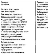
Schematic diagrams measurements are shown in Fig. 1-3.
Measuring circuit for a single bridge with a double-clamp connection
Crap. 1
Single bridge measurement circuit with double-clamp connection and electrical resistance to compensate for the electrical resistance of the wires connecting the cable product to the bridge
Crap. 2
(Changed edition, Amendment No. 1).
Double bridge measurement circuit
Crap. 3
Designations on the devil. 1-3.
E - direct current source; A - ammeter; G - galvanometer; "E - electrical resistance that limits the current; r - rheostat; P - switch for measuring the direction of the current during measurement; R1, R2, R"1, R"2, R"3 - electrical resistance of the bridge arms; K1, K2 - keys for turning on and off the galvanometer and protective electrical resistance; RN - reference electrical resistance; Rk - electrical resistance
GOST 7229-76
Group E49
INTERSTATE STANDARD
CABLES, WIRES AND CORDS
Method for determining electrical resistance
current-carrying cores and conductors
Cables, wires and cords.
Method of measuring electrical resistance of conductors
ISS 29.060.01
Date of introduction 1978-01-01
INFORMATION DATA
1. DEVELOPED by the All-Union Scientific Research Design and Technological Institute of the Cable Industry (VNIIKP)
INTRODUCED by the Ministry of Electrical Industry
2. APPROVED AND ENTERED INTO EFFECT by Resolution of the State Committee of Standards of the Council of Ministers of the USSR dated July 29, 1976 N 1844
3. The standard fully complies with ST SEV 2783-80
4. INSTEAD GOST 7229-67
5. The validity period was lifted according to Protocol No. 3-93 of the Interstate Council for Standardization, Metrology and Certification (IUS 5-6-93)
6. EDITION with Amendment No. 1, approved in September 1981 (IUS 11-81)
This standard applies to cable products and establishes a method for determining the direct current electrical resistance of current-carrying cores and conductors of cables, wires and cords, as well as wires, tapes and busbars.
The method does not apply to cable products in an installed state.
1. SAMPLING METHOD
1. SAMPLING METHOD
1.1. The measurement is carried out on construction lengths of cables, wires and cords or on straightened samples of wires, cords, wires, tapes and tires with a length of at least 1 m in the measured part, unless a different length is specified in the standards or technical specifications for specific products.
The error in measuring the construction length of a cable product should not be more than 1%.
The measurement error for cable product samples with a length of more than 1 m should not be more than 0.5%, and for samples with a length of 1 m - more than 0.2%.
1.2. Selection of samples for measurements is carried out by random selection.
1.3. The number of samples for measurements must be specified in the standards or technical specifications for specific products.
2. EQUIPMENT
2.1. Measurement of the electrical resistance of current-carrying cores and conductors must be made with a single, double or single-double constant voltage bridge with an instrumental error of no more than 0.2%.
Schematic diagrams of measurements are shown in Figures 1-3.
(Changed edition, Amendment No. 1).
2.2. When measuring using a double bridge circuit, the value of electrical resistance should not exceed the sum of the reference and measured resistances.
2.3. Depending on the value of the measured electrical resistance, measurements must be made in accordance with the table.
Damn.1. Measuring circuit for a single bridge with a double-clamp connection
Damn.2. Single bridge measurement circuit with double-clamp connection and electrical resistance to compensate for the electrical resistance of the wires connecting the cable product to the bridge
Damn.3. Double bridge measurement circuit
Explanation for drawings 1-3:
DC source; - ammeter; - galvanometer; - electrical resistance that limits the current; - rheostat; - switch for measuring the direction of current during measurement; , , , , - electrical resistance of the bridge arms; , - keys for turning the galvanometer and protective electrical resistance on and off; - reference electrical resistance; - electrical resistance, which serves to compensate for the electrical resistance of the wires connecting the cable product to the bridge; - electrical resistance of the wire connecting the reference and measured electrical resistance of the double bridge; - protective electrical resistance of the galvanometer; - measured electrical resistance
Measured electrical resistance, Ohm | Bridge type and connection diagram |
100.0 or more | Single with double-clamp connection of measured electrical resistance |
Double or single with double-clamp connection of the measured electrical resistance |
|
1.0 or less | Double with four-clamp connection of measured electrical resistance |
2.4. To measure electrical resistance, it is allowed to use automatic and other equivalent devices that carry out measurements on direct current with the error specified in clause 2.1.
3. PREPARATION FOR MEASUREMENT
3.1. Before connecting to the measuring circuit, the ends of the wires of cable products must be stripped and insulated from all metal elements not included in the measuring circuit.
3.2. The places where aluminum conductors are connected to the current contacts of the measuring circuit must be cleaned of oxide film. All wires of the stranded aluminum core must be securely connected to the current contacts of the measuring circuit.
It is allowed to connect only the top layer of a stranded aluminum core to the current contacts of the measuring circuit, provided that all wires are welded or connected by other methods to each other at the ends.
3.3. Before measurement, samples of cable products must be straightened in such a way that there is no change in the cross-sectional area of the core on which the measurement is carried out.
3.4. The holding time of the product before measuring the electrical resistance of current-carrying conductors in the room must be at least 6 hours. It is allowed to withstand construction lengths and samples of cable products for less than 6 hours if, according to the measurement results, the electrical resistance meets the requirements of standards or technical specifications for specific cable products.
In case of disagreement, samples of cable products must be kept for at least 6 hours in a room at a temperature environment in which during this time it does not differ from the ambient temperature at the time of measurement by more than 1 °C.
3.5. The ambient temperature must be measured with an error of no more than ±1 °C at a distance of no more than 1 m from the product being measured at the height of the measuring device when the product is located at the same height or at a height of 1 m from the floor if the measurement is carried out on a cable product wound on the drum.
4. MEASUREMENTS
4.1. Measurements should be carried out in a room with a temperature of 5 to 35 °C and a relative humidity of no more than 80%, unless other conditions are specified in the standards or technical specifications for cable products.
(Changed edition, Amendment No. 1).
4.2. Measurements of electrical resistances less than 10 Ohms should be carried out directly one after the other with two opposite directions of the same measuring current.
4.3. The measuring current density should be no more than 1 A/mm, and the electric current should not exceed 20 A.
In the case of determining the influence of the measuring current on the heating of the sample, two consecutive measurements must be carried out with an interval of 5 minutes without turning off the measuring current. The difference in the electrical resistance values of the sample obtained from these two measurements should not exceed twice the permissible error of the measuring device. If the specified values are exceeded, the measuring current density should be reduced.
(Changed edition, Amendment No. 1).
4.4. (Deleted, Amendment No. 1).
5. PROCESSING RESULTS
5.1. The value of the measured electrical resistance must be calculated using the formulas:
- for single bridge
For double bridge
where is the value of the measured electrical resistance, Ohm;
, , or - the values of the electrical resistance of the bridge arms at its equilibrium, Ohm.
(Changed edition, Amendment No. 1).
5.2. The arithmetic mean value of the measurement results for two opposite directions of the measuring current is taken as the result.
5.3. The electrical resistance of the wires connecting the measured product to the bridge with a two-clamp connection scheme is taken into account only if this electrical resistance is more than 0.2% of the electrical resistance of the cable product, the value of which in this case should be calculated using the formula
where is the electrical resistance of the cable product, Ohm;
- the total electrical resistance of the connecting wires when the ends to which the cable product is connected are short-circuited, Ohm.
When using a double bridge with a four-clamp connection, the electrical resistance of the wires connecting the product being measured with the electrical resistance of the bridge arms and a value of more than 0.05 Ohm must be added to the electrical resistance of the comparison store and.
In all other cases, the electrical resistance of the wires connecting the cable product to the bridge is not taken into account.
5.4. The measured value of electrical resistance must be recalculated to a temperature of 20 °C using the formula
where is the electrical resistance at a temperature of 20 °C, Ohm;
- temperature at which the measurement was carried out, °C;
- electrical resistance measured at temperature, Ohm;
- temperature coefficient of electrical resistance, °C, equal to:
0.00393 - for soft copper (annealed),
0.00381 - for solid copper,
0.00403 - for aluminum;
- temperature multiplier, the value of which for copper grades MM, MT and aluminum is given in the appendix.
If necessary, the measured value of electrical resistance can be recalculated for a length of 1 km.
When measuring the electrical resistance of current-carrying cores and conductors made of other metals, the value of the temperature coefficient of electrical resistance must be indicated in the standards or technical specifications for cable products
5.5. Specific volumetric electrical resistance of the product, Ohm m, normalized to a temperature of 20 °C, is calculated using the formula
Where -
cross-sectional area, mm;
- length of the cable product, m.
5.3-5.5. (Changed edition, Amendment No. 1).
APPENDIX (reference)
APPLICATION
Information
Temperature multiplier |
|||
Temperature, °C | Copper grades | Aluminum |
|
The text of the document is verified according to:
official publication
Cables, wires and cords.
Test methods: Sat. GOST. -
M.: IPK Standards Publishing House, 2003
GOST 7229-76
UDC 621.315.2/.3:621.317.33:006.354 Group E49
INTERSTATE STANDARD OF THE UNION OF THE USSR
CABLES, WIRES AND CORDS
METHOD FOR DETERMINING ELECTRICAL RESISTANCE OF CURRENT-CONDUCTING CORES AND CONDUCTORS
Cables, wires and cords.
Method of measuring electrical resistance of conductors
Date of introduction 01/01/78
INFORMATION DATA
1. DEVELOPED by the All-Union Scientific Research Design and Technological Institute of the Cable Industry (VNIIKP)
INTRODUCED by the Ministry of Electrical Industry
2. APPROVED AND ENTERED INTO EFFECT by Resolution of the State Committee of Standards of the Council of Ministers of the USSR dated July 29, 1976 No. 1844
3. The standard fully complies with ST SEV 2783-80
4. INSTEAD GOST 7229-67
5. The validity period was lifted according to Protocol No. 3-93 of the Interstate Council for Standardization, Metrology and Certification (IUS 5-6-93)
6. EDITION (October 2002) with Change No. 1, approved in September 1981 (IUS 11-81)
This standard applies to cable products and establishes a method for determining the direct current electrical resistance of current-carrying cores and conductors of cables, wires and cords, as well as wires, tapes and busbars.
The method does not apply to cable products in an installed state.
1. SAMPLING METHOD
1.1. The measurement is carried out on construction lengths of cables, wires and boreholes or on straightened samples of wires, cords, wires, tapes and tires with a length of at least 1 m in the measured part, unless a different length is specified in the standards or technical specifications for specific products.
The error in measuring the construction length of a cable product should be no more than 1%.
The measurement error for cable product samples with a length of more than 1 m should be no more than 0.5%, and for samples with a length of 1 m - no more than 0.2%.
1.2. Selection of samples for measurements is carried out by random selection.
1.3. The number of samples for measurements must be specified in the standards or technical specifications for specific products.
2. EQUIPMENT
2.1. Measurement of the electrical resistance of current-carrying cores and conductors must be made with a single, double or single-double constant voltage bridge with an instrumental error of no more than 0.2%.
Schematic diagrams of measurements are shown in Fig. 1-3.
(Changed edition, Amendment No. 1).
Measuring circuit for a single bridge with a double-clamp connection
Crap. 1
Single bridge measurement circuit with double-clamp connection and electrical resistance to compensate for the electrical resistance of the wires connecting the cable product to the bridge
Crap. 2
Double bridge measurement circuit
Crap. 3
Explication to hell. 1-3.
E - DC source; A - ammeter; G - galvanometer; r E - electrical resistance that limits the current; r – rheostat; P - switch for measuring the direction of current during measurement; R 1, R 2, R" 1, R" 2, R" 3 - electrical resistance of the bridge arms; K1, K2 - keys for turning the galvanometer and protective electrical resistance on and off; R N - reference electrical resistance; Rk - electrical resistance, which serves to compensate for the electrical resistance of the wires connecting the cable product to the bridge; r 2 - electrical resistance of the wire connecting the reference and measured electrical resistance of the double bridge; r 1 - protective electrical resistance of the galvanometer; R X - measured electrical resistance
2.2. When measured using a double bridge circuit, the electrical resistance value r 2 should not exceed the sum of the reference and measured resistances.
2.3. Depending on the value of the measured electrical resistance, measurements must be made in accordance with the table.
Measured electrical resistance, Ohm |
Bridge type and connection diagram |
||
100.0 or more |
Single with double-clamp connection of the measured resistance |
1.0 or less |
Double with four-clamp connection of measured electrical resistance |
99,9-1,0 |
Double or single with double-clamp connection of the measured electrical resistance |
2.4. To measure electrical resistance, it is allowed to use automatic and other equivalent instruments that perform measurements on direct current with the error specified in clause 2.1.
3. PREPARATION FOR MEASUREMENT
3.1. Before connecting to the measuring circuit, the ends of the wires of cable products must be stripped and insulated from all metal elements not included in the measuring circuit.
3.2. The places where aluminum conductors are connected to the current contacts of the measuring circuit must be cleaned of oxide film. All wires of the stranded aluminum core must be securely connected to the current contacts of the measuring circuit.
It is allowed to connect only the top layer of a stranded aluminum core to the current contacts of the measuring circuit, provided that all wires are welded or connected by other methods to each other at the ends.
3.3. Before measurement, samples of cable products must be straightened in such a way that there is no change in the cross-sectional area of the core on which the measurement is made.
3.4. The holding time of the product before measuring the electrical resistance of current-carrying conductors in the room must be at least 6 hours. It is allowed to withstand construction lengths and samples of cable products for less than 6 hours if, according to the measurement results, the electrical resistance meets the requirements of standards or technical specifications for specific cable products.
If any disagreement arises, before measurement, samples of cable products must be kept for at least 6 hours in a room where the ambient temperature during this time does not differ from the ambient temperature at the time of measurement by more than 1°C.
3.5. The ambient temperature must be measured with an error of no more than ±1°C at a distance of no more than 1 m from the product being measured at the height of the measuring device and the product is located at the same height or at a height of 1 m from the floor if the measurement is made on a cable product wound on the drum.
4. MEASUREMENTS
4.1. Measurements must be made in a room with a temperature from 5 to 35 °C and a relative humidity of no more than 80%, unless other conditions are specified in the standards or technical specifications for cable products.
(Changed edition, Amendment No. 1).
4.2. Measurements of electrical resistances less than 10 Ohms should be made directly one after the other with two opposite directions of the same measuring current.
4.3. The measuring current density should be no more than 1 A/mm 2 , and the electric current should not exceed 20 A.
In the case of determining the influence of the measuring current on the heating of the sample, two consecutive measurements must be carried out with a time interval of 5 minutes without turning off the measuring current. The difference in the electrical resistance values of the sample obtained from these two measurements should not exceed twice the permissible error of the measuring device. If the specified values are exceeded, the measuring current density should be reduced.
(Changed edition, Amendment No. 1).
4.4. (Deleted, Amendment No. 1).
5. PROCESSING RESULTS
5.1. The value of the measured electrical resistance must be calculated using the formulas:
for single bridge
for double bridge
where R x - the value of the measured electrical resistance, Ohm;
R 1, R 2, R 3 or R n - values of electrical resistance of the bridge armsat its equilibrium, Om.
(Changed edition, Amendment No. 1).
5.2. The arithmetic mean value of the measurement results for two opposite directions of the measuring current is taken as the result.
5.3. The electrical resistance of the wires connecting the measured product to the bridge with a two-clamp connection scheme is taken into account only if this electrical resistance is more than 0.2% of the electrical resistance of the cable product, the value of which in this case should be calculated using the formula
R ed = R x – R p,
where R ed. - electrical resistance of the cable product, Ohm;
R p - the total electrical resistance of the connecting wires when the ends to which the cable product is connected are short-circuited, Ohm.
When using a double bridge with a four-clamp connection, the electrical resistance of the wires connecting the measured product with the electrical resistance of the bridge arms R 1 and R" 1 value greater than 0.05 Ohm, must be added to the electrical resistance of the comparison store R 2 and R" 2.
In all other cases, the electrical resistance of the wires connecting the cable product to the bridge is not taken into account.
5.4. The measured value of electrical resistance must be recalculated to a temperature of 20 °C using the formula
R 20 = R t · K ; ,
where R 20 - electrical resistance at a temperature of 20 °C, Ohm;
t- temperature at which the measurement was made, °C;
Rt - electrical resistance measured at temperature t , Ohm;
α R - temperature coefficient of electrical resistance, C -1 equal to:
0.00393 - for soft copper (annealed),
0.00381 - for solid copper,
0.00403 - for aluminum;
K- temperature multiplier, the value of which for copper grades MM and MT and aluminum is given in the reference appendix.
If necessary, the measured value of electrical resistance can be recalculated for a length of 1 km.
When measuring the electrical resistance of current-carrying cores and conductors made of other metals, the value of the temperature coefficient of electrical resistance must be indicated in the standards or technical specifications for cable products.
5.5. Specific volumetric electrical resistance of the productρ in Ohm m, reduced to a temperature of 20°C, is calculated using the formula
where S - cross-sectional area, mm 2 ;
l - length of the cable product, m.
5.3-5.5. (Changed edition, Amendment No. 1).
APPLICATION
Information
Temperature multiplier, K |
|||||||||||||||||||||||||||||||||||||||||||||||||||||||||||||||||||||||||||||||||||||||||||||||||||||||||||||||||||||||||||||||||||||||||||||||||||||||||||||||||||||||||||||||||||||||||||||||||||||||||||||||||||||||||||||||||||||||||||||||||||||||||||||||||||||||||
Temperature, °C |
Copper grade |
Aluminum |
|||||||||||||||||||||||||||||||||||||||||||||||||||||||||||||||||||||||||||||||||||||||||||||||||||||||||||||||||||||||||||||||||||||||||||||||||||||||||||||||||||||||||||||||||||||||||||||||||||||||||||||||||||||||||||||||||||||||||||||||||||||||||||||||||||||||
MM |
MT |
||||||||||||||||||||||||||||||||||||||||||||||||||||||||||||||||||||||||||||||||||||||||||||||||||||||||||||||||||||||||||||||||||||||||||||||||||||||||||||||||||||||||||||||||||||||||||||||||||||||||||||||||||||||||||||||||||||||||||||||||||||||||||||||||||||||||
1,0626 |
1,0606 |
1,0643 |
|||||||||||||||||||||||||||||||||||||||||||||||||||||||||||||||||||||||||||||||||||||||||||||||||||||||||||||||||||||||||||||||||||||||||||||||||||||||||||||||||||||||||||||||||||||||||||||||||||||||||||||||||||||||||||||||||||||||||||||||||||||||||||||||||||||||
1,0604 |
1,0585 |
1,0621 |
|||||||||||||||||||||||||||||||||||||||||||||||||||||||||||||||||||||||||||||||||||||||||||||||||||||||||||||||||||||||||||||||||||||||||||||||||||||||||||||||||||||||||||||||||||||||||||||||||||||||||||||||||||||||||||||||||||||||||||||||||||||||||||||||||||||||
1,0582 |
1,0563 |
1,0598 |
|||||||||||||||||||||||||||||||||||||||||||||||||||||||||||||||||||||||||||||||||||||||||||||||||||||||||||||||||||||||||||||||||||||||||||||||||||||||||||||||||||||||||||||||||||||||||||||||||||||||||||||||||||||||||||||||||||||||||||||||||||||||||||||||||||||||
1,0560 |
1,0542 |
1,0575 |
|||||||||||||||||||||||||||||||||||||||||||||||||||||||||||||||||||||||||||||||||||||||||||||||||||||||||||||||||||||||||||||||||||||||||||||||||||||||||||||||||||||||||||||||||||||||||||||||||||||||||||||||||||||||||||||||||||||||||||||||||||||||||||||||||||||||
1,0538 |
1,0521 |
1,0553 |
|||||||||||||||||||||||||||||||||||||||||||||||||||||||||||||||||||||||||||||||||||||||||||||||||||||||||||||||||||||||||||||||||||||||||||||||||||||||||||||||||||||||||||||||||||||||||||||||||||||||||||||||||||||||||||||||||||||||||||||||||||||||||||||||||||||||
1,0517 |
1,0500 |
1,0531 |
|||||||||||||||||||||||||||||||||||||||||||||||||||||||||||||||||||||||||||||||||||||||||||||||||||||||||||||||||||||||||||||||||||||||||||||||||||||||||||||||||||||||||||||||||||||||||||||||||||||||||||||||||||||||||||||||||||||||||||||||||||||||||||||||||||||||
1,0495 |
1,0479 |
1,0508 |
|||||||||||||||||||||||||||||||||||||||||||||||||||||||||||||||||||||||||||||||||||||||||||||||||||||||||||||||||||||||||||||||||||||||||||||||||||||||||||||||||||||||||||||||||||||||||||||||||||||||||||||||||||||||||||||||||||||||||||||||||||||||||||||||||||||||
1,0473 |
1,0458 |
1,0486 |
|||||||||||||||||||||||||||||||||||||||||||||||||||||||||||||||||||||||||||||||||||||||||||||||||||||||||||||||||||||||||||||||||||||||||||||||||||||||||||||||||||||||||||||||||||||||||||||||||||||||||||||||||||||||||||||||||||||||||||||||||||||||||||||||||||||||
1,0452 |
1,0433 |
1,0464 |
|||||||||||||||||||||||||||||||||||||||||||||||||||||||||||||||||||||||||||||||||||||||||||||||||||||||||||||||||||||||||||||||||||||||||||||||||||||||||||||||||||||||||||||||||||||||||||||||||||||||||||||||||||||||||||||||||||||||||||||||||||||||||||||||||||||||
1,0430 |
1,0417 |
1,0442 |
|||||||||||||||||||||||||||||||||||||||||||||||||||||||||||||||||||||||||||||||||||||||||||||||||||||||||||||||||||||||||||||||||||||||||||||||||||||||||||||||||||||||||||||||||||||||||||||||||||||||||||||||||||||||||||||||||||||||||||||||||||||||||||||||||||||||
1,0409 |
1,0396 |
1,0420 |
|||||||||||||||||||||||||||||||||||||||||||||||||||||||||||||||||||||||||||||||||||||||||||||||||||||||||||||||||||||||||||||||||||||||||||||||||||||||||||||||||||||||||||||||||||||||||||||||||||||||||||||||||||||||||||||||||||||||||||||||||||||||||||||||||||||||
10,5 |
1,0388 |
1,0376 |
1,0398 |
||||||||||||||||||||||||||||||||||||||||||||||||||||||||||||||||||||||||||||||||||||||||||||||||||||||||||||||||||||||||||||||||||||||||||||||||||||||||||||||||||||||||||||||||||||||||||||||||||||||||||||||||||||||||||||||||||||||||||||||||||||||||||||||||||||||
1,0367 |
1,0355 |
1,0376 |
|||||||||||||||||||||||||||||||||||||||||||||||||||||||||||||||||||||||||||||||||||||||||||||||||||||||||||||||||||||||||||||||||||||||||||||||||||||||||||||||||||||||||||||||||||||||||||||||||||||||||||||||||||||||||||||||||||||||||||||||||||||||||||||||||||||||
11,5 |
1,0346 |
1,0335 |
1,0355 |
||||||||||||||||||||||||||||||||||||||||||||||||||||||||||||||||||||||||||||||||||||||||||||||||||||||||||||||||||||||||||||||||||||||||||||||||||||||||||||||||||||||||||||||||||||||||||||||||||||||||||||||||||||||||||||||||||||||||||||||||||||||||||||||||||||||
1,0325 |
1,0314 |
1,0333 |
|||||||||||||||||||||||||||||||||||||||||||||||||||||||||||||||||||||||||||||||||||||||||||||||||||||||||||||||||||||||||||||||||||||||||||||||||||||||||||||||||||||||||||||||||||||||||||||||||||||||||||||||||||||||||||||||||||||||||||||||||||||||||||||||||||||||
12,5 |
1,0304 |
1,0294 |
1,0312 |
||||||||||||||||||||||||||||||||||||||||||||||||||||||||||||||||||||||||||||||||||||||||||||||||||||||||||||||||||||||||||||||||||||||||||||||||||||||||||||||||||||||||||||||||||||||||||||||||||||||||||||||||||||||||||||||||||||||||||||||||||||||||||||||||||||||
1,0283 |
1,0274 |
1,0290 |
|||||||||||||||||||||||||||||||||||||||||||||||||||||||||||||||||||||||||||||||||||||||||||||||||||||||||||||||||||||||||||||||||||||||||||||||||||||||||||||||||||||||||||||||||||||||||||||||||||||||||||||||||||||||||||||||||||||||||||||||||||||||||||||||||||||||
13,5 |
1,0262 |
1,0254 |
1,0269 |
||||||||||||||||||||||||||||||||||||||||||||||||||||||||||||||||||||||||||||||||||||||||||||||||||||||||||||||||||||||||||||||||||||||||||||||||||||||||||||||||||||||||||||||||||||||||||||||||||||||||||||||||||||||||||||||||||||||||||||||||||||||||||||||||||||||
1,0241 |
1,0234 |
1,0248 |
|||||||||||||||||||||||||||||||||||||||||||||||||||||||||||||||||||||||||||||||||||||||||||||||||||||||||||||||||||||||||||||||||||||||||||||||||||||||||||||||||||||||||||||||||||||||||||||||||||||||||||||||||||||||||||||||||||||||||||||||||||||||||||||||||||||||
14,5 |
1,0221 |
1,0214 |
1,0227 |
||||||||||||||||||||||||||||||||||||||||||||||||||||||||||||||||||||||||||||||||||||||||||||||||||||||||||||||||||||||||||||||||||||||||||||||||||||||||||||||||||||||||||||||||||||||||||||||||||||||||||||||||||||||||||||||||||||||||||||||||||||||||||||||||||||||
1,0200 |
1,0194 |
1,0206 |
|||||||||||||||||||||||||||||||||||||||||||||||||||||||||||||||||||||||||||||||||||||||||||||||||||||||||||||||||||||||||||||||||||||||||||||||||||||||||||||||||||||||||||||||||||||||||||||||||||||||||||||||||||||||||||||||||||||||||||||||||||||||||||||||||||||||
15,5 |
1,0180 |
1,0174 |
1,0185 |
||||||||||||||||||||||||||||||||||||||||||||||||||||||||||||||||||||||||||||||||||||||||||||||||||||||||||||||||||||||||||||||||||||||||||||||||||||||||||||||||||||||||||||||||||||||||||||||||||||||||||||||||||||||||||||||||||||||||||||||||||||||||||||||||||||||
1,0160 |
1,0155 |
1,0164 |
|||||||||||||||||||||||||||||||||||||||||||||||||||||||||||||||||||||||||||||||||||||||||||||||||||||||||||||||||||||||||||||||||||||||||||||||||||||||||||||||||||||||||||||||||||||||||||||||||||||||||||||||||||||||||||||||||||||||||||||||||||||||||||||||||||||||
16,5 |
1,0139 |
1,0135 |
1,0143 |
||||||||||||||||||||||||||||||||||||||||||||||||||||||||||||||||||||||||||||||||||||||||||||||||||||||||||||||||||||||||||||||||||||||||||||||||||||||||||||||||||||||||||||||||||||||||||||||||||||||||||||||||||||||||||||||||||||||||||||||||||||||||||||||||||||||
1,0119 |
1,0116 |
1,0122 |
|||||||||||||||||||||||||||||||||||||||||||||||||||||||||||||||||||||||||||||||||||||||||||||||||||||||||||||||||||||||||||||||||||||||||||||||||||||||||||||||||||||||||||||||||||||||||||||||||||||||||||||||||||||||||||||||||||||||||||||||||||||||||||||||||||||||
17,5 |
1,0099 |
1,0096 |
1,0102 |
||||||||||||||||||||||||||||||||||||||||||||||||||||||||||||||||||||||||||||||||||||||||||||||||||||||||||||||||||||||||||||||||||||||||||||||||||||||||||||||||||||||||||||||||||||||||||||||||||||||||||||||||||||||||||||||||||||||||||||||||||||||||||||||||||||||
1,0079 |
1,0077 |
1,0081 |
|||||||||||||||||||||||||||||||||||||||||||||||||||||||||||||||||||||||||||||||||||||||||||||||||||||||||||||||||||||||||||||||||||||||||||||||||||||||||||||||||||||||||||||||||||||||||||||||||||||||||||||||||||||||||||||||||||||||||||||||||||||||||||||||||||||||
18,5 |
1,0059 |
1,0057 |
1,0061 |
||||||||||||||||||||||||||||||||||||||||||||||||||||||||||||||||||||||||||||||||||||||||||||||||||||||||||||||||||||||||||||||||||||||||||||||||||||||||||||||||||||||||||||||||||||||||||||||||||||||||||||||||||||||||||||||||||||||||||||||||||||||||||||||||||||||
1,0039 |
1,0038 |
1,0040 |
|||||||||||||||||||||||||||||||||||||||||||||||||||||||||||||||||||||||||||||||||||||||||||||||||||||||||||||||||||||||||||||||||||||||||||||||||||||||||||||||||||||||||||||||||||||||||||||||||||||||||||||||||||||||||||||||||||||||||||||||||||||||||||||||||||||||
19,5 |
1,0020 |
1,0019 |
1,0020 |
||||||||||||||||||||||||||||||||||||||||||||||||||||||||||||||||||||||||||||||||||||||||||||||||||||||||||||||||||||||||||||||||||||||||||||||||||||||||||||||||||||||||||||||||||||||||||||||||||||||||||||||||||||||||||||||||||||||||||||||||||||||||||||||||||||||
1,000 |
1,000 |
1,000 |
|||||||||||||||||||||||||||||||||||||||||||||||||||||||||||||||||||||||||||||||||||||||||||||||||||||||||||||||||||||||||||||||||||||||||||||||||||||||||||||||||||||||||||||||||||||||||||||||||||||||||||||||||||||||||||||||||||||||||||||||||||||||||||||||||||||||
20,5 |
0,9980 |
0,9981 |
0,9980 |
||||||||||||||||||||||||||||||||||||||||||||||||||||||||||||||||||||||||||||||||||||||||||||||||||||||||||||||||||||||||||||||||||||||||||||||||||||||||||||||||||||||||||||||||||||||||||||||||||||||||||||||||||||||||||||||||||||||||||||||||||||||||||||||||||||||
0,9961 |
0,9962 |
0,9960 |
|||||||||||||||||||||||||||||||||||||||||||||||||||||||||||||||||||||||||||||||||||||||||||||||||||||||||||||||||||||||||||||||||||||||||||||||||||||||||||||||||||||||||||||||||||||||||||||||||||||||||||||||||||||||||||||||||||||||||||||||||||||||||||||||||||||||
|
STATE STANDARD OF THE USSR UNION CABLES, WIRES AND CORDS METHOD FOR DETERMINING ELECTRICAL RESISTANCE GOST 7229-76 USSR STATE COMMITTEE ON STANDARDS Moscow DEVELOPED All-Union Scientific Research Design and Technological Institute of the Cable Industry (VNIIKP) Director I.B. Peshkov Topic LeaderL.E. Makarov Responsible executorA.A. Krotkov INTRODUCED by the Ministry of Electrical Industry Member of the Board Yu.A. Nikitin PREPARED FOR APPROVAL by the All-Union Scientific Research Institute of Standardization (VNIIS) Director A.V. Glichev APPROVED AND ENTERED INTO EFFECT by Resolution of the State Committee of Standards of the Council of Ministers of the USSR dated July 29, 1976, No. 1844 STATE STANDARD OF THE USSR UNION By Resolution of the State Committee of Standards of the Council of Ministers of the USSR dated July 29, 1976 No. 1844, the introduction date was established from 01/01/78 Verified in 1983. By Decree of the State Standard of June 15, 1983 No. 2551, the validity period was extended until 01/01/94 Failure to comply with the standard is punishable by law This standard applies to cable products and establishes a method for determining the direct current electrical resistance of current-carrying cores and conductors of cables, wires and cords, as well as wires, tapes and busbars. The method does not apply to cable products in an installed state. The standard fully complies with ST SEV 2783-80. 1. SAMPLING METHOD1.1 . The measurement is carried out on construction lengths of cables, wires and boreholes or on straightened samples of wires, cords, wires, tapes and tires with a length of at least 1 m in the measured part, unless a different length is specified in the standards or technical specifications for specific products. The error in measuring the construction length of a cable product should be no more than 1%. The measurement error for cable product samples with a length of more than 1 m should be no more than 0.5%, and for samples with a length of 1 m - no more than 0.2%. (Changed edition, Amendment No. 1). 1.2 . Selection of samples for measurements is carried out by random selection. 1.3 . The number of samples for measurements must be specified in the standards or technical specifications for specific products. 2. EQUIPMENTE- direct current source; A- ammeter; G- galvanometer; rE- electrical resistance that limits the current; r- rheostat; P- switch for measuring the direction of current during measurement; R 1 , R 2 , R" 1 , R" 2 , R" 3 - electrical resistance of the bridge arms; K 1 , K 2 - keys for turning on and off the galvanometer and protective electrical resistance; R N - reference electrical resistance; R k - electrical resistance, which serves to compensate for the electrical resistance of the wires connecting the cable product to the bridge; r 2 - electrical resistance of the wire connecting the reference and measured electrical resistance of the double bridge; r 1 - protective electrical resistance of the galvanometer; R X - measured electrical resistance 2.2 . When measured using a double bridge circuit, the electrical resistance valuer 2 should not exceed the sum of the reference and measured electrical resistances. 2.3 . Depending on the value of the measured electrical resistance, measurements must be made in accordance with the table.
2.4 . To measure electrical resistance, it is allowed to use automatic and other equivalent instruments that take measurements on direct current with the error specified in paragraph. . 3. PREPARATION FOR MEASUREMENT3.1 . Before connecting to the measuring circuit, the ends of the wires of cable products must be stripped and insulated from all metal elements not included in the measuring circuit. 3.2 . The places where aluminum conductors are connected to the current contacts of the measuring circuit must be cleaned of oxide film. All wires of the stranded aluminum core must be securely connected to the current contacts of the measuring circuit. It is allowed to connect only the top layer of a stranded aluminum core to the current contacts of the measuring circuit, provided that all wires are welded or connected by other methods to each other at the ends. 3.3 . Before measurement, samples of cable products must be straightened in such a way that there is no change in the cross-sectional area of the core on which the measurement is made. 3.4 . The holding time of the product before measuring the electrical resistance of current-carrying conductors in the room must be at least 6 hours. It is allowed to withstand construction lengths and samples of cable products for less than 6 hours if, according to the measurement results, the electrical resistance meets the requirements of standards or technical specifications for specific cable products. If any disagreement arises, before measurement, samples of cable products must be kept for at least 6 hours in a room where the ambient temperature during this time does not differ from the ambient temperature at the time of measurement by more than 1 °C. 3.5 . The ambient temperature must be measured with an error of no more than ±1 °C at a distance of no more than 1 m from the product being measured at the height of the measuring device and the product is located at the same height or at a height of 1 m from the floor if the measurement is made on a cable product wound on the drum. 4. MEASUREMENTS4.1 . Measurements must be made in a room with a temperature from 5 to 35 °C and a relative humidity of no more than 80%, unless other conditions are specified in the standards or technical specifications for cable products. (Changed edition, Amendment No. 1). 4.2 . Measurements of electrical resistances less than 10 Ohms should be made directly one after the other with two opposite directions of the same measuring current. 4.3 . The measuring current density should be no more than 1 A/mm 2, and the electric current should not exceed 20 A. In the case of determining the influence of the measuring current on the heating of the sample, two consecutive measurements must be carried out with a time interval of 5 minutes without turning off the measuring current. The difference in the electrical resistance values of the sample obtained from these two measurements should not exceed twice the permissible error of the measuring device. If the specified values are exceeded, the measuring current density should be reduced. (Changed edition, Amendment No. 1). 4.4 . (Deleted, Amendment No. 1). 5. PROCESSING RESULTS5.1 . The value of the measured electrical resistance must be calculated using the formulas: for single bridge for double bridge Where R X - value of measured electrical resistance, Ohm, R 1 , R 2 , R 3 or R n , Ohm - values of the electrical resistance of the bridge arms when it is in equilibrium. (Changed edition, Amendment No. 1). 5.2 . The arithmetic mean value of the measurement results for two opposite directions of the measuring current is taken as the measurement result. 5.3 . The electrical resistance of the wires connecting the measured product to the bridge with a two-clamp connection scheme is taken into account only if this electrical resistance is more than 0.2% of the electrical resistance of the cable product, the value of which in this case should be calculated using the formula R ed = R X - R n, Where R ed. - electrical resistance of the cable product, Ohm; R n - the total electrical resistance of the connecting wires when the ends to which the cable product is connected are short-circuited, Ohm. When using a double bridge with a four-clamp connection, the electrical resistance of the wires connecting the measured product with the electrical resistance of the bridge armsR 1 and R" 1 value greater than 0.05 Ohm, must be added to the electrical resistance of the comparison storeR 2 and R" 2 . In all other cases, the electrical resistance of the wires connecting the cable product to the bridge is not taken into account. (Changed edition, Amendment No. 1). 5.4 . The measured value of electrical resistance must be recalculated to a temperature of 20 °C using the formula R 20
= R t ×
K;
Where R 20 - electrical resistance at a temperature of 20 °C, Ohm; t- temperature at which the measurement was made, °C; R t - electrical resistance measured at temperaturet, Ohm; a R - temperature coefficient of electrical resistance,° C -1 equal to: 0 .00393 - for soft copper (annealed), 0 .00381 - for solid copper, 0 .00403 - for aluminum; K- temperature multiplier, the value of which for copper grades MM and MT and aluminum is given in the reference appendix. If necessary, the measured value of electrical resistance can be recalculated for a length of 1 km. When measuring the electrical resistance of current-carrying cores and conductors made of other metals, the value of the temperature coefficient of electrical resistance must be indicated in the standards or technical specifications for cable products. 5.3 , 5.4(Changed edition, Amendment No. 1). 5.5 . Specific volumetric electrical resistance of the productr in Ohm × m, reduced to a temperature of 20 °C, is calculated using the formula Where S- cross-sectional area, mm 2; l- length of the cable product, m. (New edition, Amendment No. 1). APPLICATIONInformation
Main
| |||||||||||||||||||||||||||||||||||||||||||||||||||||||||||||||||||||||||||||||||||||||||||||||||||||||||||||||||||||||||||||||||||||||||||||||||||||||||||||||||||||||||||||||||||||||||||||||||||||||||||||||||||||||||||||||||||||||||||||||||||||||||||||||||||||||||