Rectangular thread GOST Thread profiles - thread cutting. Image and designation of threads in the drawings
Consider standard threads general purpose.
Metric thread is the main fastening thread. This is a single-start thread, mostly right-handed, with large or small pitch. The metric thread profile is an equilateral triangle. The protrusions and protrusions of the thread are blunted (Fig. 204) (GOST 9150-81).
Rice. 204 Metric thread
Cylindrical pipe thread has a profile in the form of an isosceles triangle with an apex angle of 55° (Fig. 205), the peaks and valleys are rounded. This thread is used in pipelines and pipe connections (GOST 6351-81).

Rice. 205 Cylindrical pipe thread
Trapezoidal thread serves to transmit movement and effort. The profile of a trapezoidal thread is an isosceles trapezoid with an angle between the sides of 30° (Fig. 206). For each diameter, the thread can be single-start or multi-start, right-handed or left-handed (GOST 9484-81).

Rice. 206 Trapezoidal thread
Thread persistent has a profile of an unequal trapezoid (Fig. 207). The profile depressions are rounded and there are three different pitches for each diameter. Serves to transmit movement with large axial loads (GOST. 10177-82).

Rice. 207 Thread persistent
Round thread for bases and sockets, for safety glasses and lamps, for sanitary fittings (GOST 13536-68) has a profile obtained by pairing two arcs of the same radius (Fig. 208) (GOST 13536-68).

Rice. 208 Round thread
Conical inch thread with a profile angle of 60° (GOST 6111-52) is used for hermetic connections in pipelines of machines and machines; cut on a conical surface with a taper of 1: 16 (Fig. 209).

Rice. 209 Tapered inch thread
Conical pipe thread has a profile similar to the profile of a cylindrical pipe thread; used in valves and gas cylinders. It is possible to connect pipes having a conical thread (taper 1: 16) with products having a cylindrical pipe thread (GOST 6211-81).
Special threads- these are threads with a standard profile, but different from the standard diameter or thread pitch, and threads with a non-standard profile.
Non-standard threads - square and rectangular(Fig. 210) - are manufactured according to individual drawings, on which all thread parameters are specified.

Rice. 210 Non-standard threads
Thread image in the drawing is carried out in accordance with GOST 2.311-68. On the rod, the threads are depicted with solid main lines along the outer diameter and solid thin lines along the inner diameter. In Fig. 211, and the thread on the cylinder is shown, and in Fig. 211, b - on a cone.

Rice. 211 Image of thread in the drawing
In the hole, the threads are depicted with solid main lines along the internal diameter and solid thin lines along the outer diameter. In Fig. 212, and the thread is shown in a cylindrical hole, and in Fig. 212, b - conical.

Rice. 212 Image of thread in hole
In images obtained by projecting a threaded surface onto a plane perpendicular to its axis, a continuous thin line is drawn with an arc 3/4 of the circumference, open anywhere, but not ending at the axes. When depicting a thread, a solid thin line is drawn at a distance of at least 0.8 mm from the main line and no more than the thread pitch. The visible thread boundary is drawn as a solid base line at the end of the full thread profile to the line of the outer diameter of the thread. The thread run-out is depicted as a solid thin line, as shown in Fig. 213.

Rice. 213 Thread run-out
Chamfers on a threaded rod or in a threaded hole that do not have a special structural purpose are not depicted in projection onto a plane perpendicular to the axis of the rod or hole. A solid thin line of the thread image should intersect the chamfer boundary line (Fig. 213, 214). Hatching in sections and sections is brought to a solid main line.

Rice. 214 The thread image line must intersect the chamfer boundary line
A thread with a non-standard profile is depicted as shown in Fig. 215, with all dimensions and additional data with the addition of the word "thread".

Rice. 215 Image of a thread with a non-standard profile
In threaded connections, the thread is conventionally drawn on the rod, and in the hole - only that part of the thread that is not covered by the rod (Fig. 216).

Rice. 216 Threaded connections
The thread designation includes: thread type, size, thread pitch and stroke, tolerance range, accuracy class, thread direction, standard number.
The type of thread is conventionally designated:
M- metric thread (GOST 9150-81);
G- cylindrical pipe thread (GOST 6357-81);
T g- trapezoidal thread (GOST 9484-81);
S- thrust thread (GOST 10177-82);
Rd- round thread (GOST 13536-68);
R- external conical pipe (GOST 6211-81);
Rr- internal conical (GOST 6211-81);
Rp- internal cylindrical (GOST 6211-81);
TO- conical inch thread (GOST 6111-52).
Size of Tapered Threads and Straight Pipe Threads conventionally indicated in inches (1" = 25.4 mm), for all other threads outside diameter threads are indicated in millimeters.
Thread pitch is not indicated for metric threads with coarse pitch and for inch threads; in other cases it is indicated. For multi-start threads, the thread designation includes the thread lead, and the pitch is indicated in parentheses.
Thread direction indicate only for left-hand threads (LH).
The tolerance field and thread accuracy class may not be indicated on training drawings.
Table 1.2.1
| № p/p |
Thread type | Thread profile (some parameters) |
Conditional image threads | Standard | Notation examples | Examples of threaded connection designations |
| 1 | 2 | 3 | 4 | 5 | 6 | 7 |
| 1 | Metric | |||||
| 2 | Metric conical |  |
 |
|||
| 3 | Pipe cylindrical |  |
 |
|||
| 4 | Pipe conical |  |
||||
| 5 | Conical inch |  |
||||
| 6 | Trapezoidal |  |
||||
| 7 | Persistent |  |
||||
| 8 | Round |  |
||||
| 9 | Rectangular |
1.2.1. Metric thread
Metric thread (see Table 1.2.1) is the main type of fastening thread. The thread profile is established by GOST 9150-81 and is an equilateral triangle with a profile angle α = 60°. The thread profile on the rod differs from the thread profile in the hole in the amount of blunting of its peaks and valleys. The main parameters of metric threads are: nominal diameter - d(D)
and thread pitch - R, installed by GOST 8724-81.
According to GOST 8724-81, each nominal thread size with a large pitch corresponds to several small steps. Threads with fine pitch are used in thin-walled connections to increase their tightness, to carry out adjustments in precision mechanics and optics devices, in order to increase the resistance of parts to self-unscrewing. In the event that the diameters and pitches of threads cannot satisfy the functional and design requirements, ST SEV 183-75 “Metric threads for instrument construction” was introduced. If one diameter corresponds to several step values, then large steps are used first. The diameters and pitches of threads indicated in brackets are not used if possible.
In the case of using conical metric (see Table 1.2.1) threads with a taper of 1:16, the thread profile, diameters, pitches and main dimensions are established by GOST 25229-82. When connecting an external conical thread with an internal cylindrical thread according to GOST 9150-81, it must be ensured that the external conical thread is screwed in to a depth of at least 0.8.
1.2.2. Inch thread
Currently, there is no standard regulating the main dimensions of inch threads. The previously existing OST NKTP 1260 has been canceled, and the use of inch threads in new developments is not allowed.
Inch threads are used when repairing equipment, since parts with inch threads are in use. The main parameters of an inch thread are: the outer diameter, expressed in inches, and the number of steps per inch of the length of the cut part of the part.
1.2.3. Pipe cylindrical thread
In accordance with GOST 6367-81, a cylindrical pipe thread has an inch thread profile, i.e. an isosceles triangle with an apex angle of 55° (see Table 1.2.1).
Threads are standardized for diameters from 1/16" to 6" in number of pitches z from 28 to 11. The nominal thread size is conventionally related to the internal diameter of the pipe (to the nominal diameter). Thus, a thread with a nominal diameter of 1 mm has a nominal diameter of 25 mm, and an outer diameter of 33.249 mm.
Pipe threads are used to connect pipes, as well as thin-walled cylindrical parts. This kind of profile (55°) is recommended for increased requirements for the tightness (tightness) of pipe connections. Pipe threads are used when connecting the cylindrical threads of the coupling with the conical threads of pipes, since in this case there is no need for various seals.
1.2.4. Pipe tapered thread
The parameters and dimensions of conical pipe threads are determined by GOST 6211-81, according to which the thread profile corresponds to the profile of an inch thread (see Table 1.2.1). The thread is standardized for diameters from 1/16" to 6" (in the main plane, the thread dimensions correspond to the dimensions of a cylindrical pipe thread).
Threads are cut on a cone with a taper angle j/2 = 1°47"24" (as for a metric tapered thread), which corresponds to a taper of 1:16.
The thread is used for threaded connections of fuel, oil, water and air pipelines of machines and machine tools.
1.2.5. Trapezoidal thread
Trapezoidal thread has the shape of an isosceles trapezoid with an angle between the sides equal to 30° (see Table 1.2.1). The main dimensions of diameters and pitches of trapezoidal single-start threads for diameters from 10 to 640 mm are established by GOST 9481-81. Trapezoidal threads are used to convert rotational motion into translational motion under significant loads and can be single- and multi-start (GOST 24738-81 and 24739-81), as well as right and left.
1.2.6. Thrust thread
The thrust thread, standardized by GOST 24737-81, has a profile of an unequal trapezoid, one of the sides of which is inclined to the vertical at an angle of 3°, i.e. the working side of the profile, and the other at an angle of 30° (see Table 1.2. 1). The profile shape and pitch diameters for persistent single-start threads are established by GOST 10177-82. The thread is standardized for diameters from 10 to 600 mm with pitches from 2 to 24 mm and is used for large unilateral forces acting in the axial direction.
1.2.7. Round thread
Round threads are standardized. The profile of a round thread is formed by arcs connected to each other by sections of a straight line. The angle between the sides of the profile is α = 30° (see table 1.2.1). Threads are used to a limited extent: for water supply fittings, in some cases for crane hooks, and also under conditions of exposure to aggressive environments.
1.2.8. Rectangular thread
Rectangular threads (see Table 1.2.1) are not standardized, since, along with the advantages of a higher efficiency than trapezoidal threads, they are less durable and more difficult to manufacture. Used in the manufacture of screws, jacks and lead screws.
1.3. Conventional image of a thread. GOST 2.311-68
Constructing a helical surface in a drawing is a long and complex process, therefore, in product drawings, threads are depicted conditionally, in accordance with GOST 2.311-68. The helix line is replaced by two lines - a solid main line and a solid thin line.
Threads are divided according to their location on the surface of the part into external and internal.
1.3.1. Conventional image of a thread on a rod

Fig.1.3.1.1
The external thread on the rod (Fig. 1.3.1.1) is depicted by solid main lines along the outer diameter and solid thin lines along the internal diameter, and in images obtained by projection onto a plane perpendicular to the axis of the rod, a thin line is drawn at 3/4 of the circle , and this line can be open anywhere (it is not allowed to start a solid thin line and end it on the center line). The distance between the thin line and the solid main line should not be less than 0.8 mm and greater than the thread pitch, and the chamfer is not shown in this view. The thread boundary is applied at the end of the full thread profile (before the start of the run) with a solid main line, if it is visible. If necessary, the thread run-out is depicted as a solid thin line.

Fig.1.3.1.2?
For technological reasons, a part of the part (rod) may be under-threaded. In total, the undercut of the thread and the run-out represent an undercut of the thread (GOST 10548-80). The thread length is indicated, as a rule, without runoff.
1.3.2. Conventional image of a thread in a hole

Fig.1.3.2.1
Internal thread - is depicted by a solid main line along the inner diameter and a solid thin line along the outer diameter. If, when depicting a blind hole, the end of the thread is located close to its bottom, then it is allowed to depict the thread to the end of the hole. Threads with a non-standard profile should be depicted.
1.3.3. Conventional image of the assembled thread

Fig.1.3.3.1
Sections of a threaded connection in the image on a plane parallel to its axis in the hole show only that part of the thread that is not covered by the thread of the rod.
Hatching in sections and sections is carried out to a solid main line, i.e. to the outer diameter of the male thread and the internal diameter of the female thread.
1.4. Conventional image of threads
Table 1.4.1
| Thread type | Symbol for thread type | Dimensions indicated in the drawing | Thread designation on drawings | |||
| in images in a plane parallel to the thread axis | in images in a plane perpendicular to the thread axis | |||||
| on the rod | In the hole | on the rod | In the hole | |||
|
Metric with large pitch GOST 9150-81 |
M | Outer diameter (mm) |
||||
|
Metric with fine pitch GOST 9150-81 |
M | |||||
|
Trapezoidal single-thread GOST 9484-81 (ST SEV 146-78) |
Tr | Outer diameter and thread pitch (mm) | ||||
|
Pipe cylindrical GOST 6357-81 (ST SEV 1157-78) |
G | |||||
|
Conical inch GOST 6111-52 |
K | Designation in inches | ||||
|
Pipe conical GOST 6211-81 (ST SEV 1159-78): external and internal |
R Rc |
Designation in inches | ||||
To designate threads, they use standards for individual thread types. For all threads, except conical and cylindrical pipe threads, the designations refer to the outer diameter and are placed above the dimension line, on its extension or on the shelf of the leader line. Designations of conical threads and cylindrical pipe threads are applied only on the shelf of the leader line.
The thread in the drawing is conventionally designated in accordance with the standards for image, diameters, pitches, etc.
Metric threads are designated in accordance with GOST 9150-81.
Metric thread is divided into threads with a large pitch, designated by the letter M indicating the nominal diameter of the cylindrical surface on which the thread is made, for example M12, and a thread with a fine pitch, indicated by indicating the nominal diameter, thread pitch and tolerance range, for example M24 × 2-6g or M12 × 1-6H.
When designating a left-hand thread, LH is placed after the symbol.
Multi-start threads are designated, for example, three-start, M24×Z(P1)LH, where M- thread type, 24 - nominal diameter, 3 - thread stroke, P 1 - thread pitch. The given designations for left-handed and multi-start threads can be applied to all metric threads.
Metric tapered thread designated in accordance with GOST 25229-82. The thread designation includes the letters MK. Connections of internal cylindrical threads with external conical threads are used. The dimensions of the profile elements of conical and cylindrical threads are taken in accordance with GOST 9150-81. A connection of this type must ensure screwing in a conical thread to a depth of at least 0.8 l(Where l- thread length without run). The designation of an internal cylindrical thread consists of the nominal diameter, pitch and standard number (for example: M20×1.5 GOST 25229-82).

Fig.1.4.1
The connection of an internal cylindrical thread with an external conical thread (Fig. 1.4.1) is designated by the fraction M/MK, nominal diameter, pitch and standard number: M/MK 20×1.5LH GOST 25229-82. With absence special requirements to the density of connections of this kind or when using seals to achieve tightness of such connections, the standard number in the designation of connections is omitted, for example: M/MK 20 × 1.5 LH.
The tolerance field of the average diameter of the internal cylindrical thread must correspond to 6N according to GOST 16093-81, and the maximum deviation of the internal diameter and cut of the cavities of the internal cylindrical thread is accepted within the following limits: upper limit deviation (+0.12) -g - (+0.15), and the lower limit deviation is 0.
Pipe cylindrical thread. The thread symbol consists of the letter G, designation of thread size, accuracy class of average diameter ( A or IN). For left-hand threads, the symbol LH is used. For example, G1½LH-B-40 make-up length, indicated if necessary.
The connection of an internal cylindrical pipe thread of accuracy class A with an external pipe conical thread according to GOST 6211-81 is designated as follows: for example, G/Rp-1½-A.
When designating fits, the numerator indicates the accuracy class of the internal thread, and the denominator indicates the external thread. For example: G 1½-A/B.
Tapered pipe thread. The thread designation includes the following letters: R- for tapered external threads, R c - for tapered internal thread, R p - for cylindrical internal thread and designation of thread size. For left-hand threads, the letters LH are added. The nominal size of the thread, as well as its diameters measured in the main plane, correspond to the parameters of a cylindrical pipe thread having the same nominal size. Therefore, parts with conical pipe threads are often used in connections with parts with cylindrical pipe threads, which ensures a fairly high tightness of the connections. Threaded connections are designated as a fraction, the numerator of which indicates the letter designation of the internal thread, and the denominator - the external thread. Example of designation:
G/R * 1½ - A
— internal pipe cylindrical thread of accuracy class A according to GOST 6357-81.
Trapezoidal thread.Symbol trapezoidal thread consists of letters Tr, nominal diameter, stroke R n and step R. For example: Tr20×4LH-8H, where LH is the designation of the left-hand thread, 8H is the main thread deviation.
If necessary, after the main thread deviation, the make-up length is indicated L(in mm). For example: Tg40×6-8g-85; 85 - make-up length.
The thread is persistent. The thread designation consists of the letter S, nominal diameter, pitch and main deviation S80×10-8N.
For left-hand threads, the letters LH are indicated after the thread symbol.
For multi-start threads, enter an additional stroke value together with the letter R and step value. Thus, a double-start thread with a pitch of 10 mm is designated S80 × 2 (P10).
Rectangular thread not standardized. When depicting a rectangular thread, it is recommended to draw a local section on which the required dimensions are marked.
Special threads. If the thread has a standard profile, but differs from the corresponding standard thread in diameter or pitch, then the thread is called special. In this case, the inscription is added to the thread designation Sp, and in the thread designation the dimensions of the outer diameter and thread pitch are indicated, for example: Sp.M19×1D A thread with a non-standard profile is depicted as presented in paragraph 9 of Table 1, with the dimensions required for manufacturing threading.
Parts in machines and mechanisms are connected to each other in some way. These connections perform various functions. Connections are divided into two types: movable and fixed, which, in turn, are divided into detachable and permanent.
Detachable are connections that can be reassembled and disassembled without damaging (destructing) them components. These include threaded, keyed, pin, splined and other types of connections.
5.1 Threads
Thread- a surface formed by the helical movement of a flat contour along a cylindrical or conical surface.
5.1.1 Classification
By purpose threads are divided into fastening(in a fixed connection) and running gear or kinematic (in a mobile connection). Often fastening threads have a second function - sealing the threaded connection and ensuring its tightness.
Depending from the shape of the surface, on which the thread is cut, it can be cylindrical or conical.
Depending from surface location thread may be outdoor(cut on a rod) or internal(cut into hole).
Depending from profile shape distinguish threads triangular, trapezoidal, rectangular, round, special.
Triangular thread is divided into metric , pipe , conical inch, trapezoidal thread - on trapezoidal , stubborn , stubborn reinforced .
By step size There are large, small and special threads.
By number of visits threads are divided into single-pass And multi-pass .
In the direction of the helix distinguish threads right(the thread is cut clockwise) and left(the thread is cut counterclockwise).
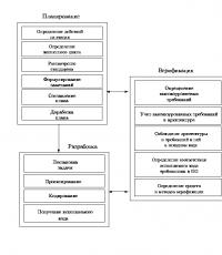
Figure 5.1 - Classification of threads
5.1.2 Profiles and thread parameters
5.1.2.1 Thread profiles
A thread is formed by the screw movement of a certain flat figure, which defines the so-called thread profile, located in the same plane with the axis of the surface of rotation (thread axis).
Thread profiles characterized by the following features:
- metric thread has a profile in the form of an equilateral triangle with an angle at the apex 60 0 (Figure 5.2). Metric threads are cylindrical and conical;
- pipe thread has a profile in the form of an isosceles triangle with an angle at the apex 55 0 (Figure 5.2). Pipe threads can also be cylindrical or conical;
- conicalinch thread has a profile in the form of an equilateral triangle (Figure 5.2);
- round thread has a profile in the form of a semicircle;
- trapezoidal thread has a profile in the form of an isosceles trapezoid with an angle 30 0 between the sides (Figure 5.2);
- persistent thread has a profile of a non-equilateral trapezoid with an angle of inclination of the working side 3 0 and non-working - 30 0 (Figure 5.2);
- rectangular thread has a profile in the form of a rectangle (Figure 5.2). The thread is not standardized.
 |
 Metric thread (triangular) |
 |
 Cylindrical pipe thread |
 Conical pipe thread |
|
 Inch conical thread |
|
 |
 Round thread |
 Trapezoidal thread |
|
 Thread persistent |
|
 Rectangular non-standard thread |
Figure 5.2 - Types and parameters of threads
5.1.2.2 Thread parameters
Thread diameter (d) is the diameter of the surface on which the thread will be formed.
Thread pitch(P) - the distance along a line parallel to the thread axis between the midpoints of the nearest identical sides of the thread profile, lying in the same axial plane on one side of the axis of rotation (GOST 11708-82).
Thread stroke- relative axial movement of a threaded part per revolution, equal to the product nP, Where n– number of thread starts. For a single-start thread, the lead is equal to the pitch.
A thread formed by the movement of one profile is called single-pass , formed by the movement of two, three or more identical profiles is called multi-pass (two-, three-way, etc.).
5.1.3 Purpose of thread and its elements
| Thread type | Letter designation | Purpose |
|---|---|---|
| Metric | M... | General purpose threads, standard fasteners |
| Metric conical | MK... | Instrumentation |
| Trapezoidal | Tr… | Lead screws transmitting reciprocating motion |
| Persistent | S… | Mechanisms with high axial force (screw presses, jacks) |
| Pipe cylindrical | G… | Pipe connection, fittings, valves |
| Pipe conical | R… (external) Rc… (internal) |
Connecting pipes at high pressures and temperatures (increased tightness) |
| Round for electrical fittings | E... | Cartridges, sockets |
Depending on the conditions and nature of production, threading can be carried out different ways and tools. For the production of most standardized threads, thread cutting with dies or taps is widely used.
The die is used for cutting external threads on a pre-prepared workpiece, the diameter of which is determined by the diameter and pitch of the thread being cut.
The working (cutting) surface of the die has a conical intake part (chamfer) and a cylindrical calibrating part, which ensures cutting a thread of the required size. As a result of the presence of the intake part on the threaded rod, at the end of the thread there remains a section l 1 with a profile gradually decreasing in height (Figure 5.3, c). This section with incomplete threads is called thread run-out . A full profile thread, defined by the calibrating part of the die, ends on the rod where the thread starts to run out. In the case when the cut part of the rod is limited by some supporting surface (shoulder, head, shoulder, etc.), when cutting the thread (to avoid breakage) the die is usually not brought all the way to this surface.
In this case, a section called thread undercut. Escape plus undershoot form undercut thread l 2 (Figure 5.3, c).
 |
||
| A | b | V |
Figure 5.3 — Threading a rod
The tap (Figure 5.4) is used for cutting internal threads in a pre-drilled hole, the diameter d 1 of which is selected depending on the pitch and diameter of the thread being cut (see table 5.2. (GOST 19257-73. Holes for cutting metric threads)).
| Thread pitch, P | Drill diameter, d 1 | Nominal thread diameter, d | Thread pitch, P | Drill diameter, d 1 | |
|---|---|---|---|---|---|
| 1 | 0,2 | 0,80 | 10 | 0,5 | 9,50 |
| 0,25 | 0,75 | 0,75 | 9,25 | ||
| 1,1 | 0,2 | 0,90 | 1 | 9,00 | |
| 0,25 | 0,85 | 1,25 | 8,80 | ||
| 1,2 | 0,2 | 1,00 | 1,5 | 8,50 | |
| 0,25 | 0,95 | 11 | 0,5 | 10,50 | |
| 1,4 | 0,2 | 1,20 | 0,75 | 10,25 | |
| 0,3 | 1,10 | 1 | 10,00 | ||
| 1,6 | 0,2 | 1,40 | 1,25 | 9,50 | |
| 0,35 | 1,25 | 12 | 0,5 | 11,50 | |
| 1,8 | 0,2 | 1,60 | 0,75 | 11,25 | |
| 0,35 | 1,45 | 1 | 11,00 | ||
| 2 | 0,25 | 1,75 | 1,25 | 10,80 | |
| 0,4 | 1,60 | 1,5 | 10,50 | ||
| 2,2 | 0,25 | 1,95 | 1,75 | 10,20 | |
| 0,45 | 1,75 | 14 | 0,5 | 13,50 | |
| 2,5 | 0,35 | 2,15 | 0,75 | 13,25 | |
| 0,45 | 2,05 | 1 | 13,00 | ||
| 3 | 0,35 | 2,65 | 1,25 | 12,80 | |
| 0,5 | 2,50 | 1,5 | 12,50 | ||
| 3,5 | 0,35 | 3,15 | 2 | 12,00 | |
| 0,6 | 2,90 | 15 | 1 | 14,00 | |
| 4 | 0,5 | 3,50 | 1,5 | 13,50 | |
| 0,7 | 3,30 | 16 | 0,5 | 15,50 | |
| 4,5 | 0,5 | 4,00 | 0,75 | 15,25 | |
| 0,75 | 3,75 | 1 | 15,00 | ||
| 5 | 0,5 | 4,5 | 1,5 | 14,50 | |
| 0,8 | 4,20 | 2 | 14,00 | ||
| 5,5 | 0,5 | 5,00 | 17 | 1 | 16,00 |
| 6 | 0,5 | 5,50 | 1,5 | 15,50 | |
| 0,75 | 5,25 | 18 | 0,5 | 17,50 | |
| 1 | 5,00 | 0,75 | 17,25 | ||
| 7 | 0,5 | 6,50 | 1 | 17,00 | |
| 0,75 | 6,25 | 1,5 | 16,50 | ||
| 1 | 6,00 | 2 | 16,00 | ||
| 8 | 0,5 | 7,50 | 2,5 | 15,50 | |
| 0,75 | 7,25 | 20 | 0,5 | 19,50 | |
| 1 | 7,00 | 0,75 | 19,25 | ||
| 1,25 | 6,80 | 1 | 19,00 | ||
| 9 | 0,5 | 8,50 | 1,5 | 18,50 | |
| 0,75 | 8,25 | 2 | 18,00 | ||
| 1 | 8,00 | 2,5 | 17,50 | ||
| 1,25 | 7,80 |
 |
||
| A | b | V |
Figure 5.4 - Tapping a hole
Figure 5.4 shows a blind (non-through) hole. At its bottom there is a conical recess left from the drill. The angle at the apex of the cone is conventionally assumed to be equal to 120 0 , and its dimensions are not shown on the drawings.
Before cutting the thread at the end of the rod (for external threads) and at the beginning of the hole (for internal threads) chamfers , the conical surface of which forms an angle of 45 0 with the axis. The chamfer protects the outer turns from damage, simplifies the thread cutting process, and facilitates the connection of threaded parts with each other. The size of the chamfers is determined by the size of the thread pitch (Table 5.3).
The tap, like the die, has a conical intake part and a calibrating part. When cutting a thread with a tap, there will be a thread run-out, determined by the intake part of the tap, and a full profile thread. When cutting a thread in a blind hole, the tap (to avoid its breakage) is not brought all the way to the bottom of the hole, so there will be an undercut of the thread and, consequently, an undercut of the thread as the sum of the run-out and the undercut of the thread.
If you need to make a full profile thread, without a run, then to remove the thread-forming tool, make a groove, the diameter of which for external threads should be slightly less than the internal diameter of the thread (Figure 5.5, a), and for internal threads - slightly larger than the external diameter of the thread (Figure 5.5 , b).
The dimensions of chamfers, runs, undercuts, and grooves are standardized by GOST 10549-80* - Thread exit. Runs, undercuts, grooves and chamfers and GOST 27148-86 - Fasteners. Thread exit. Runaways, undercuts, grooves. Dimensions.
 |
|
| A | b |
Figure 5.5 — External and internal grooves
 |
|||||||||||
| Thread pitch P | Groove | Chamfer z | |||||||||
|---|---|---|---|---|---|---|---|---|---|---|---|
| Type 1 | Type 2 | d f | when mating with internal thread with groove type 2 | for all other cases | |||||||
| normal | narrow | ||||||||||
| f | R | R 1 | f | R | R 1 | f | R 2 | ||||
| 0 ,2 | — | — | — | — | — | — | — | — | — | — | 0 ,2 |
| 0 ,25 | |||||||||||
| 0 ,3 | |||||||||||
| 0 ,35 | d — 0 ,6 | 0 ,3 | |||||||||
| 0 ,4 | 1 ,0 | 0 ,3 | 0 ,2 | ||||||||
| 0 ,45 | d — 0 ,7 | ||||||||||
| 0 ,5 | 1 ,6 | 0 ,5 | 0,3 | 1 ,0 | 0 ,3 | 0 ,2 | d — 0 ,8 | 0 ,5 | |||
| 0 ,6 | d — 0 ,9 | ||||||||||
| 0 ,7 | 2 ,0 | 1 ,6 | 0,5 | 0,3 | d — 1,0 | ||||||
| 0 ,75 | d — 1,2 | 1 ,0 | |||||||||
| 0 ,8 | 3,0 | 1 ,0 | 0 ,5 | ||||||||
| 1 | 2 ,0 | 3 ,6 | 2 ,0 | d — 1,5 | 2 ,0 | ||||||
| 1,25 | 4 ,0 | 2 ,5 | 1 ,0 | 0 ,5 | 4 ,4 | 2 ,5 | d — 1,8 | 2 ,5 | 1 ,6 | ||
| 1 ,5 | 4,6 | d — 2 ,2 | 3 ,0 | ||||||||
| 1,75 | 5 ,4 | 3 ,0 | d — 2 ,5 | 3 ,5 | |||||||
| 2 | 5 ,0 | 1 ,6 | 3,0 | 5 ,6 | d — 3 ,0 | 2 ,0 | |||||
| 2 ,5 | 6 ,0 | 1 ,0 | 4 ,0 | 7 ,3 | 4 ,0 | d — 3 ,5 | 5 ,0 | 2 ,5 | |||
| 3 | 7 ,6 | d — 4 ,5 | 6 ,5 | ||||||||
| 3 ,5 | 8 ,0 | 2 ,0 | 5 ,0 | 1 ,6 | 10 ,2 | 5 ,5 | d — 5 ,0 | 7,5 | |||
| 4 | 10,3 | d — 6 ,0 | 8,0 | 3,0 | |||||||
| 4 ,5 | 10 ,0 | 3 ,0 | 6 ,0 | 1 ,0 | 12 ,9 | 7 ,0 | d — 6 ,5 | 9 ,5 | |||
| 5 | 13 ,1 | d — 7 ,0 | 10 ,5 | 4 ,0 | |||||||
| 5 ,5 | 12 ,0 | 8 ,0 | 2 ,0 | 15,0 | 8 ,0 | d — 8 ,0 | |||||
| 6 | 16 ,0 | 8 ,5 | d — 9 ,0 | ||||||||
5.1.4 Image and designation of threads in the drawings
The rules for depicting and applying thread designations on drawings are established by GOST 2.311-68*.
The carving is depicted:
a) on the rod - with solid main lines along the outer diameter of the thread and solid thin lines - along the inner diameter for the entire length of the thread, including the chamfer. In the images obtained by projection onto a plane perpendicular to the axis of the rod, an arc is drawn along the internal diameter of the thread with a solid thin line, equal to 3/4 of the circle, open anywhere, but not along the axes (Figure 5.6, a);
b) in the hole - with solid main lines along the internal diameter of the thread and solid thin lines - along the outer diameter. In the images obtained by projection onto a plane perpendicular to the axis of the hole, an arc is drawn along the outer diameter of the thread with a solid thin line, equal to 3/4 of the circle, open anywhere (Figure 5.6b).
 |
|
| A | b |
Figure 5.6 - Representation of threads in the drawings: external - on the rod (a), internal - in the hole (b)
A solid thin line on the image of the thread is applied at a distance of at least 0.8 mm from the main line and no more than the thread pitch. The line defining the thread boundary is drawn on the rod and in the threaded hole at the end of the full thread profile (before the start of the run). The thread boundary is drawn to the line of the outer diameter of the thread and is depicted as a solid main or dashed line if the thread is depicted as invisible (Figure 5.7, 5.8), where l st- the length of the rod on which the thread is cut, l sv— the depth of drilling the hole for the thread.

Figure 5.7 - Image of the visible thread boundary

Figure 5.8 - Image of the invisible thread border
Hatching in sections and sections is carried out to the line of the outer diameter of the thread on the rods and to the line of the internal diameter in the hole, i.e. in both cases to the solid main line.
Thread length with full profile (without run-out) l) on the rod and in the hole are indicated as shown in Figure 5.7, 5.9.
If it is necessary to indicate the amount of run-off on the rod, the dimensions are applied as shown in Figure 5.9c. The thread run-out is depicted as a solid thin line drawn either along a radius or as a segment at approximately an angle of 30 0 (Figure 5.9b).
 |
||
| A | b | V |
Figure 5.9 - Image of thread run-out, thread length size
An undercut of a thread made all the way is shown as shown in Figure 5.7. Chamfers on a threaded rod and in a threaded hole that do not have a special structural purpose are not shown in projection onto a plane perpendicular to the axis of the rod or hole (Figure 5.6, a, b). A solid thin line of the thread on the rod should intersect the chamfer boundary line.
On sections of a threaded connection in the image on a plane parallel to its axis, only the part of the thread that is not covered by the thread of the rod is shown in the hole (Figure 5.10).

Figure 5.10 - Image of a threaded connection
Thread designations indicate, according to the relevant standards, the dimensions and maximum deviations of the thread and relate them to all threads, except conical and cylindrical pipe, to the outer diameter, as shown in Figures 5.4, 5.11.
 |
|
| A | b |
Figure 5.11 — Applying dimensions to threads
The designation of tapered threads and cylindrical pipe threads is applied as shown in Figure 5.12.

Figure 5.12 — Dimensions on pipe and tapered threads
5.1.5 Mounting threads
5.1.5.1 Metric thread
Metric threads are most widely used in engineering.
The thread profile (Figure 5.2) is established in GOST 9150-81; the main dimensions (nominal values) of the outer, middle and inner thread diameters are in GOST 24705-2004; diameters and pitches - GOST 8724-81 (Appendix A) - see table 5.6.
M.Metric threads are made with large(the only one for a given thread diameter) and small in steps, which can be several for a given diameter. Therefore, in the designation of metric threads, the large pitch is not indicated, but the small pitch is required.
Designation: M20x1.5-6g - metric external thread (on the rod) with a diameter of 20 mm with a fine pitch of 1.5 mm (Fig. 5.11, a); M20 LH-6g – the same left, with a large pitch; M20x1.5 LH-6g – the same with fine pitch; M20-6N – internal thread (in the hole) with a large pitch (Fig. 5.11, b). Specifying the thread tolerance range is mandatory.
5.1.5.2 Metric tapered thread
Metric tapered thread (GOST 25229-82) is used to connect pipelines.
Designation: MK8*1 - metric conical with a diameter of 8 mm, measured in the main plane and in increments of 1 mm (Fig. 5.12, b).
5.1.5.3 Cylindrical pipe thread
Cylindrical pipe threads in accordance with GOST 6357-81 are used on water and gas pipes, parts for their connection (couplings, elbows, crosses, etc.), pipeline fittings (gate valves, etc.).
The profile of a cylindrical pipe thread is shown in Figure 5.2.
The symbol includes the letter G, thread size in inches, accuracy class of the average thread diameter - A or B (less accurate) and screwing length in mm, if it exceeds the normal one established by the standard.
Example: G 1/2 (Fig. 5.12, a), G 1/4-A, G 1/2 LH-A, G 3/8-A-20.
If for a metric thread the diameter size indicated in the designation corresponds to its actual size (without taking into account tolerance), then in a pipe thread the size in inches indicated in the designation is approximately equal to nominal diameter of the pipe(nominal internal diameter by which it is calculated throughput), converted to inches.
For example, G1 denotes the size of a pipe thread cut on the outer surface of a pipe having a nominal bore of 25 mm, i.e. approximately 1 inch. In fact, the outer diameter of the pipe is 33.249 mm, i.e. more than two pipe wall thicknesses - table 5.5.
Therefore, the designation of the pipe thread size is applied on the shelf of the leader line (Figure 5.13).

Figure 5.13 — Pipe thread designation
| Thread size inch | 1/4 | 3/8 | 1/2 | 3/4 | 1 | 1 ¼ |
|---|---|---|---|---|---|---|
| Conditional pass , mm | 9 | 10 | 15 | 20 | 25 | 40 |
| Pipe outer diameter, mm | 13,5 | 17,0 | 21,3 | 26,8 | 33,5 | 48,0 |
| Outer thread diameter, mm | 13,16 | 16,67 | 20,96 | 26,44 | 33,25 | 47,80 |
5.1.5.4 Tapered pipe thread
Tapered pipe threads in accordance with GOST 6211-81 are used in pipe connections at high pressures and temperatures, when increased tightness of the connection is required.
For thread profile, see Figure 5.2. Since the diameter of the tapered thread is constantly changing, its size is referred to the section in the main plane (approximately in the middle of the length of the external thread). In this section, the diameter of the tapered thread is equal to the diameter of the cylindrical pipe thread (Figure 5.14). The position of the main plane is indicated on the working drawing (taken from the standard).

Figure 5.14 — Designation of pipe tapered thread
External thread is designated by the letter R, internal – Rc.
The designation of a tapered pipe thread includes the letter R(Rc) and the size in inches without specifying the dimension.
Example: R 1 1/2 LH - outer left, Rс 1/8 - inner (Fig. 5.12, c).
5.1.5.5 Tapered inch thread
Conical inch threads (GOST 6111-52) are used in connections of fuel, oil, water, air pipelines of machines and machine tools at low pressures.
The designation consists of the letter TO and thread size in inches, indicating the dimension, is applied on the shelf of a leader line, as with pipe threads.
Example: To 3/4″ GOST 6111-52.
5.1.5.6 Round thread
Round threads are used for mixer valve spindles in accordance with GOST 19681-94 (Sanitary water fittings) and water taps in accordance with GOST 20275-74.
The designation for round threads includes the letters Kr, nominal thread diameter in mm, thread pitch in mm and GOST 13536-68.
Example: Kr 12x2.54 GOST 13536-68, where 2.54 is the thread pitch in mm, 12 is the nominal thread diameter in mm. GOST 13536-68 defines the profile, main dimensions and tolerances of round threads.
5.1.6 Lead threads
5.1.6.1 Trapezoidal thread
Used on screws that transmit reciprocating motion and axial force. Carving happens single-pass And multi-pass .
The thread profile is shown in Figure 5.2.
The main dimensions, diameters, pitches, tolerances of single-start threads are standardized according to GOST 24737-81, 24738-81, 9562-81.
For multi-start threads, these parameters are found in GOST 24739-81 *.
Symbol for single-start thread consists of letters Tr, values of the nominal thread diameter, pitch, tolerance range.
Example: Tr 40x6-8e - trapezoidal single-start external thread with a diameter of 40 mm with a pitch of 6 mm, Tr 40x6-8e-85 - the same make-up length 85 mm, Tr 40x6LH-7N - the same for the internal left.
IN symbol for multi-start thread the numerical value of the stroke is added: Tr 20x8(P4)-8e – trapezoidal multi-start external thread with a diameter of 20 mm with a stroke of 8 mm and a pitch of 4 mm.
5.1.6.2 Thrust thread
It is used on screws subject to unilaterally directed forces, for example in jacks.
10.1.4. Image and designation of threads in the drawings
The image and designation of threads in the drawings are standardized. In accordance with GOST 2.311-68, external threads are depicted with solid main lines along the diameter D and solid thin lines along the diameter D 1 . In images obtained by projection onto a plane perpendicular to the thread axis, a solid thin line is not extended to 1/4 . The chamfer lines are not shown (Figure 10.6).
When depicting a thread, a solid thin line is drawn at a distance of at least 0.8 mm from the main line and no more than the pitch value. A solid thin line of the thread on the rod should intersect the chamfer boundary line.
Internal threads are shown with solid main lines - along the internal diameter d and solid thin ones - along the diameter d 1 . The thread boundary is applied at the end of the full profile, before the start of the run. It is drawn to the line of the outer diameter and is depicted as a solid thick line if the thread is visible, and dashed if it is invisible. Hatching in sections and sections is carried out to a solid thick line.
For all types of threads, excluding conical and cylindrical pipe threads, the designation refers to the outer diameter and is placed above the dimension line, on its extension and on the leader shelf (Figure 10.6).
Figure 10.6 - Symbol for internal and external threads
The designation of conical threads and cylindrical pipe threads refers to the contour of the thread and is applied only on the shelf of the leader line (Figure 10.7).

Figure 10.7 - Designation of conical and cylindrical pipe threads
Table 1 - Thread types and designations
|
Profile |
Designation |
|
|
Metric GOST 9150-81 - on the profile GOST 24705-81 - for diameter sizes GOST 8724-81 - for diameters and pitches |
Equilateral triangle. The tops of the protrusions and depressions of the profile are cut along a straight line or a circular arc, which facilitates the manufacture of threads, reduces stress concentration and protects the threads from damage during operation. |
M20-6g - metric thread with a diameter of 20 mm, coarse pitch 2.5 mm, tolerance range 6g, right; M20×2- metric thread with a diameter of 20 mm, fine pitch 2 mm, right; M20×2L.H. - metric thread with a diameter of 20 mm, fine pitch 2 mm, left. The thread has one large and several small steps for each nominal diameter. The large pitch is not indicated in the thread designation, but the small pitch is required. LH is added to the left-hand thread designation. |
|
Metric threads are most widely used in technology. This thread is used on bolts, studs, screws, nuts, etc. Right-hand threads are preferably used. |
||
|
Inch GOST 6111-52 |
An isosceles triangle with an apex angle of 55° (for a tapered thread - a profile angle of 60). The peaks and valleys are cut flat. |
1" - inch cylindrical thread with an outer diameter of 1 inch; K 1 3 / 4" GOST 6111-52- inch conical thread. |
|
Pipe cylindrical GOST 6357-81 Pipe conical GOST 6211-81 |
An isosceles triangle with an apex angle of 55°. The crests and valleys are rounded, which makes the thread more airtight than metric threads. |
G1- A - cylindrical pipe thread with a diameter of 1 inch, accuracy class A; R1 - external conical pipe thread; R c1 - internal conical pipe thread. Size 1"=25.4 mm corresponds to the internal diameter of the pipe (nominal bore). The outer diameter of the pipe thread will be 1" = 25.4 mm + 2 pipe thickness = 33.25 mm. |
|
Straight pipe threads are used on water and gas pipes, on parts for their connection - fittings (couplings, elbows, tees, etc.), pipeline fittings (gate valves), etc. Tapered pipe threads are used in pipe connections at high pressures and temperatures. |
||
|
Trapezoidal GOST 9484-81 - on the profile, GOST 24738-81 - for diameters and pitches |
|
Tr40×6-8e- trapezoidal thread, single-start, with a nominal diameter of 40 mm, pitch 6 mm, accuracy class 8e; Tr48×9(RZ)LN- trapezoidal thread, three-start, with a nominal diameter of 49 mm, stroke 9 mm, pitch 3 mm, left |
|
Used on screws that transmit reciprocating motion. |
||
|
Persistent GOST 10177-82 for profile and main dimensions |
Uneven-sided trapezoid with angles of 3° and 30° at the sides |
S80×5- persistent thread, with a nominal diameter of 80 mm, single-start, with a pitch of 5 mm; S80×20(P5)LN- persistent thread, four-start, with a nominal diameter of 80 mm, stroke 20 mm, pitch 5 mm, left. |
|
Used on screws subject to unidirectional forces, for example, in jacks. |
||
|
Rectangular |
The profile is not standardized; the drawing provides all the data necessary for its manufacture. |
|
|
It is used in connections where there should be no self-unscrewing under the influence of an applied load. |
||
|
The profile is standard, but the diameter or pitch dimensions differ from those accepted by the standard. |
Sp is added to the designation of any thread with a standard profile: |
|


Thread profiles
TO category:
Threading
Thread profiles
The thread profile depends on the shape of the cutting part of the tool with which the thread is cut. The most commonly used thread is a cylindrical triangular thread (sawtooth), usually called a fastening thread; These threads are cut on fasteners such as studs, bolts and nuts.
In addition to cylindrical triangular threads, there are conical triangular threads, which make it possible to obtain a tight connection; such threads are found on conical plugs, and fittings are sometimes found in oilers.
Rectangular threads have a rectangular profile (square). It is not standardized, difficult to manufacture, fragile and rarely used.
Trapezoidal tape thread has a trapezoidal cross-section with a profile angle of 30°. It has a low coefficient of friction, and therefore this thread is used to transmit movements or large forces: in metal-cutting machines (lead screws), jacks, presses, etc. The turns of this thread have a large cross-section at the base, which ensures its high strength and convenience when cutting. The main elements of trapezoidal threads are standardized.
The thrust thread has a profile in the form of an unequal trapezoid with a working angle at the apex of 30°. The bases of the turns are rounded, which provides a strong profile in dangerous sections. Therefore, this thread is used in cases where the screw must transmit a large one-sided force (in screw presses, jacks, etc.).
A round thread has a profile formed by two arcs associated with small straight sections and an angle of 30; rarely used in mechanical engineering. It is used in connections subject to heavy wear and in contaminated environments (fittings of fire pipelines, carriage couplers, hooks of lifting machines, etc.). This thread is not standardized.
Based on the number of threads, threads are divided into single-start (single-start) and multi-start (multi-start).
The thread stroke is the axial movement of the screw per revolution. For example, when screwing, the nut will move in one revolution by an amount equal to the thread stroke. For single-start threads, the pitch is equal to the lead. For multi-start screws, the thread lead is obtained by multiplying the pitch (the distance between adjacent turns) by the number of starts. The number of starts can be determined by looking at the end of the screw (nut), which usually clearly shows how many threads originate from the end of the three-start, eight-start (Fig. 259, a, b).

Rice. 1. Profiles and thread elements: a - cylindrical triangular, b - rectangular, c - trapezoidal, d - persistent, d - round

Rice. 2. Threads with different numbers of starts (strokes): a - three-start, b - eight-start
With single-start (single-start) threads, only one end of the thread is visible at the end of the screw or nut, while with multi-start (multi-start) threads, two, three or more turns are visible.
Single-start threads have small helix angles and greater friction (low efficiency). They are used where a reliable connection is required - for fastening threads.
In multi-start threads, compared to single-start threads, the helix angle is much larger (steeper rise). Such threads are used in cases where rapid movement along the thread with the least friction is necessary, and in one turn of the screw (or nut), the nut (or screw) will move by the amount of stroke of the helical line of the thread. Multi-start threads are used in mechanisms used to transmit motion.
Main types of threads and their designation
In mechanical engineering, as a rule, three thread systems are used: metric, inch and pipe.
Metric thread has a triangular profile with flat-cut tops (Fig. 3, a) and is characterized by the following basic elements: profile angle 60°, diameters and pitch are expressed in the metric system of measures - in millimeters.
Metric threads are divided into threads with coarse pitch (for outer diameters 1-68 mm) and threads with fine pitches (for diameters 1-600 mm); steps for large threads - 0.25 - 6 mm, for small threads - 0.2 - 6 mm.
Metric threads with a large pitch are designated: M20 (the number is the outer diameter of the thread); with small steps: M20x 1.5 (the first number is the outer diameter, and the second is the pitch).
Metric threads are used mainly as fastening threads: with large pitches - for significant loads and for fasteners (bolts, nuts, screws), with small pitches - for light loads and fine adjustments.
Inch thread (Fig. 3, b, c, d) has a triangular cut profile with an angle of 55 ° (Whitworth thread) or 60 ° (Sellers thread). All dimensions of this thread are given in inches (1” = 25.4 mm). Pitch is expressed as the number of threads (turns) per inch.
Inch threads are standardized with diameters from 3/16 to 4” and the number of threads per 1” -24 - 3. Its outer diameter is indicated in inches. It differs from metric in larger steps.
In the USSR, when designing new structures, the use of inch threads is not permitted. It is used in the manufacture of spare parts for machinery and equipment obtained from countries where inch threads are used.
The cylindrical pipe thread is standardized and is a fine inch thread. Unlike inch threads, it mates without gaps (to increase the tightness of the connection) and has rounded tops.

Rice. 3. Thread systems: a - metric, 6 - inch, c - pipe, d - part with inch thread
For the nominal diameter of the pipe thread, the internal diameter of the pipe (the diameter of the hole, or, as they say, the “clear diameter of the pipe”) is used, i.e. the outer diameter of the pipe thread will be larger than the nominal diameter by twice the thickness of the pipe walls.
Cylindrical pipe threads are used for outer diameters 1/8 - 6” with the number of threads per 1” from 28 to 11. The profile angle is 55°.
Pipe cylindrical threads are used on pipes to connect them, as well as on pipeline fittings and other thin-walled parts.
Pipe cylindrical thread is designated: Pipe 3/4” (numbers are the nominal diameter of the thread in inches).
Pipe threads with a diameter from 2/8 to 6" are standardized with the number of threads per 1" - 28-11.