Development process life cycle. Life cycle of software systems
In the general case, a software system, in addition to the programs itself, also contains hardware, and is also usually considered surrounded by other software and hardware systems.
The life cycle of a software system is usually understood as the entire period of existence of a software system, starting from the moment the initial concept of the system is developed and ending when the system becomes obsolete. Concept ``life cycle"" used when the software system is expected to have a fairly long lifespan, as opposed to experimental programming in which programs are run several times and not used again.
The life cycle is traditionally modeled as a certain number of successive stages (or stages, phases). Currently, there is no generally accepted division of the life cycle of a software system into stages. Sometimes a stage is highlighted as a separate point, sometimes it is included as an integral part of a larger stage. The actions performed at one or another stage may vary. There is no uniformity in the names of these stages. Therefore, we will first try to describe some generalized life cycle of a software system, and then demonstrate several examples of different life cycles, indicating analogies from this generalized cycle.
Software life cycle stages
The software life cycle is the period of software development and operation, which usually includes the following stages: -1- emergence and research of an idea; -2- requirements analysis and design; -3- programming; -4- testing and debugging; -5- putting the program into effect; -6- operation and maintenance; -7- end of operation.
It should be noted that breaking the life cycle into stages sometimes helps to obscure some important aspects of software creation; This is especially true in relation to such a necessary process as the iterative implementation of various stages of the life cycle in order to correct errors, change decisions that turned out to be incorrect, or take into account changes in the overall requirements for the system.
Examples of life cycle descriptions
Let's look at several descriptions of the software life cycle, which will serve as a kind of commentary on the stages of the generalized life cycle.
In domestic regulatory documents (for example, GOST ESPD), the following division into stages is adopted, which is given with an indication of analogies from the list given at the beginning of the section:
development of technical specifications (stages 1 and 2);
technical design (third stage up to 3.2.1 inclusive);
working draft (3.2.2, 4.2.1 and, in part, 4.2, 4.3);
pilot implementation (4.2 and 4.3);
commissioning for commercial operation (stage 5);
industrial operation (stage 6).
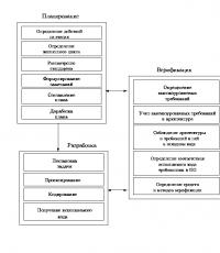
Such a description is based on hardware development technology and therefore does not fully take into account all the distinctive features of software design. A more appropriate description of the software life cycle appears to be 12 stages, which are very similar to the stages of the generalized life cycle (see Figure 1.1). In parentheses after the name of the phase, an analogue from the generalized cycle is indicated. Almost all stages end with verification of the results obtained at the corresponding stage.
Rice. 1.1 Example of the life cycle of software systems
Project initiation and planning (stage 1). The necessary actions, plans and organization of project management are determined. Measures are determined to ensure the continuous execution of life cycle phases.
Analysis of target requirements (2.1). The general characteristics of the system that it must satisfy are determined, without taking into account the means of implementation. It is established what the system should do and how it should do it.
Analysis of system requirements (2.2). It describes how the user's requests should be satisfied, in terms of specific functional concepts, the actions of the proposed system, the stored data, the interface used are described - all this without taking into account the physical implementation. The suitability of these specific concepts is tested.
System design (3.1). The structure of the system or, in other words, its architecture is established in terms of the main components of this system and their intended implementation (hardware, software, using the environment, etc.). Requirements for each component are established, as well as a testing and integration strategy.
Preliminary software design (3.2.1). Determination of specific software components that will be developed and implemented in the final system. Checking this set of components for consistency with general software requirements. Determination of functional, operational and test requirements for each specific component.
Detailed software design (3.2.2). In terms of the software constructs used, a description is made of how each specific component will be developed. The modes of use of each component in the system are described.
Software coding and testing (4.1.1 and 4.1.2). Creation, testing of individual modules, documentation and acceptance of software components that make up the software system.
Software integration (part 4.2). Testing the performance and functional completeness of the software parts of the system in a predictable environment (hardware and environment).
System integration (4.3). Testing the performance and functional completeness of parts of the overall system as a whole.
Acceptance and delivery of the system (5). The system is accepted by the customer and the system is delivered to him.
Operation and maintenance of the system (6). Release of subsequent versions or versions of the system, the need for which arises due to the elimination of defects, testing of changed requirements, etc.
Completion of the project (7). Formation of a post-origin model of project actions with an analysis of advantages, disadvantages, etc., and using them as a basis for improving the development process.
As the next example, consider an incomplete software life cycle, without operation and maintenance stages (see Fig. 1.2). This option does not fix the sequence of phases or stages, but rather proposes a list of actions that must be performed throughout the software life cycle. These actions can be broken down or, conversely, grouped into different stages, depending on specific conditions. The following stages of the life cycle of software systems can be distinguished (in parentheses, as before, are analogues from the generalized cycle model):
the planning stage, which determines and coordinates the activities to develop the software system (stage 1);
development stage at which a software system is created:
problem statement (stage 2),
design (3),
coding (4.1.1),
getting executable code (4.1.1, 4.3);
an integrated stage that ensures correction, verification, and determination of the completeness of the software system, as well as its release. This stage includes verification, monitoring the system configuration, quality assessment and checking the interaction between the stages. From the name of this stage it is clear that it is performed in conjunction with other stages throughout the life cycle of the system.

Rice. 1.2 Option for a simplified life cycle of a software system.
The absence of an integrated stage in the general life cycle does not mean that verification is carried out only where this is clearly indicated in the name of the stage (for example, 4.2.1 and 4.2). Each stage can be considered completed only when the results obtained at this stage are considered satisfactory, and for this it is necessary to check the results at each stage. In the summary life cycle, some checks have been highlighted as separate items to demonstrate the increased volume, complexity and importance of these checks.
The sequence of life cycle stages for different software systems is determined by such characteristics as functionality, complexity, size, stability, use of previously obtained results, the strategy being developed, and hardware.
In Fig. 1.3. shows the sequence of stages of software development for individual components of a single software system with different life cycles.

Rice. 1.3 Sequence of stages of development of software components
For component W, from the set of system requirements for a single product, a subset of requirements related to this component is formed, these requirements are used when forming a project for a software component, this project is implemented in source code, and then the component is integrated with the hardware. Component X shows the use of previously developed software. Component Y shows the use of a simple single function that can be coded directly based on the software requirements. Component Z shows the use of the prototype strategy. Typically, the goals of prototyping are to better understand software requirements and reduce technical and development risks in creating the final product. The initial requirements are used as the basis for obtaining a prototype. This prototype is converted into an environment typical for the specific development use of the system. The result of the transformation is refined data that is used to create the final software product.
Almost all stages of the life cycle are combined with verification.
Software life cycle
One of the basic concepts of IS design methodology is the concept of software life cycle (SOLC).
J C– this is a model of various states of a software product, starting from the moment the need for this software product arises and ending with the moment it goes out of use for all users.
The life cycle of databases is not yet regulated by standards - existing standards relate only to the life cycle of software.
PS life cycle standards can be used as directive, guidance or advisory documents.
The life cycle, technology for developing and ensuring the quality of software are most fully reflected in ISO standards (International Standards Organization). The ISO 12207:1995 standard - “Software life cycle processes” - most fully reflects the architecture, work, organization and management of the software life cycle.
The software life cycle models actually used in companies have recently changed relative to those given in the standards due to the introduction and development of object-oriented analysis and methods for rapid software development, CASE systems and fourth-generation languages. The new models reduce the work on the direct creation of software components and detail the work on system analysis and design of software systems and databases.
In general, when creating PS projects and ensuring their life cycle, it is advisable to use a sample from the entire set of presented standards (both international and national), and fill existing gaps in standardization with de facto standards and departmental regulatory documents.
Profile is a set of several basic standards and other regulatory documents intended to implement a given function or group of functions.
Based on the same set of basic standards, different profiles can be formed for different projects.
When certifying information systems, certification for compliance with the profile is distinguished as a special type of test. And here it should be taken into account that in international IP standardization a strict interpretation of the concept of a profile is adopted - it is believed that only international and national approved standards can be the basis of a profile (that is, the use of de facto standards and regulatory documents of companies is not allowed).
Based on the specific profile, it is planned to write documentation. Moreover, for each stage of the life cycle, its own documentation is written, which in turn is divided into types, depending on for which specialists it is created.
Software life cycle is a continuous process that begins from the moment a decision is made about the need for its creation and ends at the moment of its complete withdrawal from service.
The main regulatory document regulating the life cycle of software is the international standard ISO /IEC 12207 (ISO - International Organization of Standardization, IEC - International Electrotechnical Commission). It defines the life cycle structure containing the processes, activities and tasks that must be performed during software creation.
The structure of the software life cycle according to the ISO / IEC 12207 standard is based on three groups of processes:
· main processes Software life cycle (purchase, supply, development, operation, support);
· auxiliary processes ensuring the implementation of basic processes (documentation, configuration management, quality assurance, verification, certification, assessment, audit, problem solving);
· organizational processes(project management, creation of project infrastructure, definition, evaluation and improvement of the life cycle itself, training).
Development includes all work on creating software and its components in accordance with specified requirements, including the preparation of design and operational documentation, preparation of materials necessary to test the functionality and appropriate quality of software products, materials necessary for organizing personnel training, etc.
Software development includes, usually:
· analysis;
· design;
· implementation (programming).
The development phase begins with a feasibility study of the project and then translates it from user requirements into a form that can be implemented on computers.
This phase typically accounts for 50% of the design cost and 32% of labor costs.
Exploitation begins when the product is handed over to the user, in use and in use.
Includes:
Work on putting software components into operation, including configuring the database and user workstations;
Providing operational documentation;
Conducting personnel training, etc., and direct operation, including localizing problems and eliminating the causes of their occurrence,
Modification of software within the established regulations, preparation of proposals for improvement, development and modernization of the system.
Maintenance phase also called the ongoing development phase.
Consists of identifying and eliminating errors in programs and changing their functionality.
Practitioners have recognized that this part of the life cycle (LC) should be taken into account from the moment development begins in order to improve the design in accordance with the needs of the user.
Maintenance process, will continue in parallel with the operation of the PI.
The structure of labor costs for various types of support activities is such that about 78% of the time is spent on changing the functionality of the software, and 17% on identifying errors.
Configuration management is one of the auxiliary processes that support the main processes of the software life cycle, primarily the processes of software development and maintenance. When creating complex IS projects consisting of many components, each of which may have varieties or versions, the problem arises of taking into account their connections and functions, creating a unified structure and ensuring the development of the entire system. Configuration management allows you to organize, systematically take into account and control changes to software at all stages of the life cycle. General principles and recommendations for configuration accounting, planning and software configuration management are reflected in the draft standard ISO 12207-2.
Project quality assurance associated with problems of software verification, verification and testing. Verification is the process of determining whether the current state of development achieved at a given stage meets the requirements of that stage. Examination allows you to assess the compliance of development parameters with the initial requirements. The check partially coincides with testing, which is associated with identifying differences between actual and expected results and assessing the compliance of software characteristics with initial requirements. In the process of project implementation, an important place is occupied by the issues of identification, description and control of the configuration of individual components and the entire system as a whole.
Project management associated with issues of planning and organizing work, creating development teams and monitoring the timing and quality of work performed. Technical and organizational support for the project includes the selection of methods and tools for project implementation, determination of methods for describing intermediate development states, development of methods and tools for software testing, personnel training, etc.
Each process is characterized by:
specific tasks and methods for solving them,
the initial data obtained at the previous stage,
results.
The results of the analysis, in particular, are functional models, information models and their corresponding diagrams. Life cycle software carries iterative nature: The results of the next stage often cause changes in design solutions developed at earlier stages.
Software life cycle models
The ISO/IEC 12207 standard does not provide a specific life cycle model and software development methods. (The life cycle model depends on the specifics of the information system and the specific conditions in which the latter is created and operates). Its regulations are common to any life cycle models, methodologies and development technologies. The ISO/IEC 12207 standard describes the structure of software life cycle processes, but does not specify in detail how to implement or perform actions And tasks included in these processes.
To date, the following two main life cycle models have become most widespread:
· cascade model (70-85);
· spiral model (86-90).
In the original homogeneous IS, each application was a single whole. To develop this type of application we used cascade method. Its main characteristic is the division of the entire development into stages, and the transition from one stage to the next occurs only after the work on the current one is completely completed (Fig. 1). Each stage culminates in the release of a complete set of documentation sufficient to allow development to be continued by another development team.
The positive aspects of using the cascade approach are as follows:
· at each stage, a complete set of design documentation is generated that meets the criteria of completeness and consistency;
· stages of work carried out in a logical sequence allow us to plan the completion time of all work and the corresponding costs.
 |
|||
 |
Rice. 1. Waterfall software development scheme
The cascade approach has proven itself well in the construction of information systems, for which, at the very beginning of development, all requirements can be quite accurately and completely formulated in order to give developers the freedom to implement them as best as possible from a technical point of view. Complex calculation systems, real-time systems, and other similar tasks fall into this category. However, in the process of using this approach, a number of its shortcomings were discovered, primarily caused by the fact that the real software creation process never completely fit into such a rigid scheme:
· Identifying reasons why a project needs to be changed at later stages: checking the functionality and feasibility of an application project in the early stages is usually not performed.
· Inadequate risk management: risks associated with the project are identified in the later stages of the project.
· No procedure for reviewing requirements: In this model, requirements must be formulated and recorded in the early stages of development. As a rule, project goals and objectives are not fully understood at the beginning of the project, and therefore they have to be revised at later stages, which leads to a significant increase in development costs and delays in product release. If the changed requirements are not taken into account in the project, the customer will not consider the application to meet the objectives.
 |
Rice. 2 Real software development process using a waterfall scheme
So, the main disadvantage of the cascade approach is the significant delay in obtaining results. Coordination of results with users is carried out only at points planned after the completion of each stage of work; the requirements for the IS are “frozen” in the form of technical specifications for the entire time of its creation. Thus, users can make their comments only after work on the system is completely completed. If requirements are inaccurately stated or they change over a long period of software development, users end up with a system that does not meet their needs. Models (both functional and informational) of the automated object may become outdated simultaneously with their approval.
Thus, in the process of creating software, there was a constant need to return to previous stages and clarify or revise previously made decisions. As a result, the actual software creation process took the following form (Fig. 2):
To overcome these problems, it was proposed spiral life cycle model(Fig. 3), focusing on the initial stages of life cycle: analysis and design. At these stages, the feasibility of technical solutions is tested by creating prototypes. Each turn of the spiral corresponds to the creation of a fragment or version of software. It clarifies the goals and characteristics of the project, determines its quality, and plans the work of the next turn of the spiral. Thus, the details of the project are deepened and consistently specified, and as a result, a reasonable option is selected, which is brought to implementation.
Development by iterations reflects the objectively existing spiral cycle of creating a system. Incomplete completion of work at each stage allows you to move on to the next stage without waiting for the complete completion of the current stage. With an iterative development method, the missing work can be completed in the next iteration. The main task is to show system users a workable product as quickly as possible, thereby activating the process of clarifying and supplementing requirements.
The main problem of the spiral cycle is determining the moment of transition to the next stage. To solve it, it is necessary to introduce time restrictions for each stage of the life cycle. The transition proceeds as planned, even if not all planned work is completed. The plan is drawn up based on statistical data obtained in previous projects and the personal experience of the developers.
The spiral life cycle model places emphasis on the initial stages of the life cycle: analysis and design. At these stages, the feasibility of technical solutions is tested by creating prototypes. Each turn of the spiral corresponds to the creation of a fragment or version of the software, where the goals and characteristics of the project are clarified, its quality is determined, and the work of the next turn of the spiral is planned. In this way, the details of the project are deepened and consistently specified, and as a result, a reasonable option is selected, which is brought to implementation.

Rice. 3. Spiral life cycle model
| |
When creating software it can be used "A Model of Reuse and Reverse Engineering."
In it, the main weight of design decisions falls on design. The purpose of this model is the reuse (reuse) in current projects of well-tested “old” design solutions recorded in libraries of already completed projects. During the analysis and preliminary design process, work plans are outlined that include tasks for testing alternative design solutions. Then work begins to create the planned prototypes using a cascade scheme. As a result, one of the alternative solutions is selected, developed in parallel iterations for the remainder of the product development cycle. It is possible to select a mixed option based on combining the results of several turns.
If the implemented version fails, a rollback of the project (Reengineering) is possible.
Software development is impossible without understanding the so-called software life cycle. The average user may not need to know this, but it is advisable to master the basic standards (later it will be said why this is necessary).
What is life cycle in a formal sense?
The life cycle of any application is usually understood as the time of its existence, starting from the development stage and until the moment of complete abandonment of use in the chosen field of application, up to the complete withdrawal of the application from use.
In simple terms, information systems in the form of programs, databases or even “operating systems” are in demand only if the data and the opportunities they provide are up-to-date.
It is believed that the life cycle definition does not apply in any way to test applications, such as beta versions, which are the most unstable in operation. The software life cycle itself depends on many factors, among which one of the main roles is played by the environment in which the program will be used. However, it is possible to identify general conditions used in defining the concept of life cycle.
Initial requirements
- formulation of the problem;
- analysis of mutual requirements of future software for the system;
- design;
- programming;
- coding and compilation;
- testing;
- debugging;
- implementation and maintenance of the software product.
Software development consists of all the above-mentioned stages and cannot do without at least one of them. But special standards have been established for control of such processes.
Software Life Cycle Process Standards
Among the systems that predetermine the conditions and requirements for such processes, today we can name only three main ones:
- GOST 34.601-90;
- ISO/IEC 12207:2008;
- Oracle CDM.

For the second international standard there is a Russian analogue. This is GOST R ISO/IEC 12207-2010, which is responsible for system and software engineering. But the software life cycle described in both rules is essentially identical. This is explained quite simply.
Types of software and updates
By the way, for most currently known multimedia programs, they are a means of saving basic configuration parameters. The use of software of this type is, of course, quite limited, but understanding the general principles of working with the same media players will not hurt. And that's why.
In fact, they include the software life cycle only at the level of updating the version of the player itself or installing codecs and decoders. And audio and video transcoders are integral attributes of any audio or video system.
Example based on FL Studio
Initially, the virtual studio-sequencer FL Studio was called Fruity Loops. The life cycle of the software in its initial modification has expired, but the application has been somewhat transformed and acquired its current form.

If we talk about the stages of the life cycle, first, at the stage of setting the problem, several mandatory conditions were set:
- creating a drum module similar to rhythm machines like Yamaha RX, but using one-shot samples or sequences in WAV format, recorded live in studios;
- integration into Windows operating systems;
- the ability to export a project in WAV, MP3 and OGG formats;
- Compatibility of projects with the additional application Fruity Tracks.
At the development stage, C programming language tools were used. But the platform looked quite primitive and did not provide the end user with the required sound quality.
In this regard, at the testing and debugging stage, the developers had to follow the path of the German Steinberg corporation and apply support for Full Duplex mode in the requirements for the main sound driver. The sound quality has become higher and allows you to change the tempo, pitch and apply additional FX effects in real time.

The end of the life cycle of this software is considered to be the release of the first official version of FL Studio, which, unlike its ancestors, already had the interface of a full-fledged sequencer with the ability to edit parameters on a virtual 64-channel mixing console with unlimited addition of audio tracks and MIDI tracks.
It didn't stop there. At the project management stage, support was introduced for connecting plug-ins of the VST format (first the second, and then the third version), which was once developed by Steinberg. Roughly speaking, any virtual synthesizer that supports VST-host could connect to the program.

It is not surprising that soon any composer could use analogues of “hardware” models, for example, complete sets of sounds of the once popular Korg M1. Further more. The use of modules like Addictive Drums or the universal Kontakt plugin made it possible to reproduce the live sounds of real instruments recorded with all shades of articulation in professional studios.
At the same time, the developers tried to achieve maximum quality by creating support for ASIO4ALL drivers, which turned out to be head and shoulders above the Full Duplex mode. Accordingly, the bitrate also increased. Today, the quality of the exported audio file can be 320 kbps at a sampling rate of 192 kHz. And this is professional sound.
As for the initial version, its life cycle could be called completely complete, but such a statement is relative, since the application only changed its name and acquired new capabilities.
Development prospects
What the stages of the software life cycle are is already clear. But the development of such technologies is worth mentioning separately.
Needless to say, any software developer is not interested in creating a fleeting product that is unlikely to survive in the market for several years. In the long term, everyone is looking at its long-term use. This can be achieved in different ways. But, as a rule, almost all of them come down to the release of updates or new versions of programs.
Even in the case of Windows OS, such trends can be seen with the naked eye. It is unlikely that today there will be at least one user using systems like modifications 3.1, 95, 98 or Millennium. Their life cycle ended after the release of XP. But server versions based on NT technologies are still relevant. Even Windows 2000 today is not only very relevant, but in some installation or security parameters it even surpasses the latest developments. The same applies to the NT 4.0 system, as well as a specialized modification of Windows Server 2012.

But in relation to these systems, support is still declared at the highest level. But the once sensational Vista is clearly experiencing the decline of its cycle. Not only did it turn out to be unfinished, but there were so many errors in it and gaps in its security system that one can only guess how such an untenable solution could be released onto the software market.
But if we say that the development of software of any type (control or application) does not stand still, we can only say that today it concerns not only computer systems, but also mobile devices, in which the technologies used are often ahead of the computer sector. The emergence of processor chips based on eight cores is not the best example? But not every laptop can boast of having such hardware.
Some additional questions
As for understanding the software life cycle, it can be said very conditionally that it ended at a certain point in time, because software products still have support from the developers who created them. Rather, the ending refers to legacy applications that do not meet the requirements of modern systems and cannot run in their environment.
But even taking into account technological progress, many of them may soon become untenable. Then you will have to make a decision either to release updates or to completely revise the entire concept originally incorporated into the software product. Hence the new cycle, which involves changing the initial conditions, development environment, testing and possible long-term use in a certain area.
But in computer technology today preference is given to the development of automated control systems (ACS), which are used in production. Even operating systems, in comparison with specialized programs, lose.
Visual Basic-based environments remain much more popular than Windows systems. And we are not talking about application software for UNIX systems at all. What can we say if almost all communication networks of the same United States work exclusively for them. By the way, systems like Linux and Android were also originally created on this platform. Therefore, most likely, UNIX has much more prospects than other products combined.
Instead of a total
It remains to add that in this case only general principles and stages of the software life cycle are given. In fact, even the initially set tasks can vary very significantly. Accordingly, differences can be observed at other stages.
But the basic technologies for developing software products and their subsequent support should be clear. For the rest, one should take into account the specifics of the software being created, the environments in which it is supposed to work, and the capabilities of the programs provided to the end user or production, and much more.
In addition, sometimes life cycles can depend on the relevance of development tools. If, for example, a programming language becomes obsolete, no one will write programs based on it, much less implement them into automated production control systems. Here it is not even programmers who come to the fore, but marketers who must respond in a timely manner to changes in the computer market. And there are not so many such specialists in the world. Highly qualified personnel who can keep their finger on the pulse of the market are becoming the most in demand. And they are often the so-called “gray cardinals” on whom the success or failure of a certain software product in the IT field depends.
They may not always understand the essence of programming, but they are clearly able to determine models of the software life cycle and the length of time for their use, based on global trends in this area. Effective management often produces more tangible results. Yes, at least PR technologies, advertising, etc. The user may not need some application, but if it is actively advertised, the user will install it. This is already, so to speak, a subconscious level (the same effect of the 25th frame, when information is put into the user’s consciousness independently of him).
Of course, such technologies are prohibited in the world, but many of us do not even realize that they can still be used and influence the subconscious in a certain way. Just look at the cost of “zombification” by news channels or Internet sites, not to mention the use of more powerful means, such as exposure to infrasound (this was used in one opera production), as a result of which a person may experience fear or inappropriate emotions.
Returning to the software, it is worth adding that some programs use a sound signal when starting up to attract the user's attention. And, as research shows, such applications are more viable than other programs. Naturally, the software life cycle also increases, no matter what function was initially assigned to it. And, unfortunately, many developers use this, which raises doubts about the legality of such methods.
But it’s not for us to judge this. It is possible that tools will be developed in the near future to identify such threats. So far this is only a theory, but, according to some analysts and experts, there is very little left before practical application. If they are already creating copies of the neural networks of the human brain, then what can we say?
The software life cycle includes six stages:
- requirements analysis;
– determination of specifications;
– design;
– coding;
– testing;
– accompaniment.
Requirements analysis. It is extremely important in software development. Errors made at this stage, even if subsequent stages are carried out flawlessly, can lead to the fact that the developed software product will not meet the requirements of practice and the scope of its application. To create competitive products during this stage, clear answers to the following questions must be obtained:
– What should the program do?
– What are the real problems that it should help solve?
– What is the input data?
– What should the output data be?
– What resources does the designer have?
Defining Specifications. Specification– an accurate and complete formal description of the properties, characteristics and functions of a program, data element or other object. To a certain extent, this stage can be considered as the formulation of conclusions following from the results of the previous stage. Program requirements must be expressed as a set of specifications that explicitly define the performance characteristics of the future program. Such characteristics may include execution speed, amount of memory consumed, flexibility of use, etc.
Design. At this stage, the overall structure of the program is created, which must satisfy the specifications; the general principles of management and interaction between the various components of the program are determined.
Coding. It consists of translating structures written in a design language into a programming language.
Testing. At this stage, a comprehensive check of the programs is carried out.
Escort. This is the operating stage of the system. No matter how sophisticated program testing may be, unfortunately, in large software systems it is extremely difficult to eliminate absolutely all errors. Eliminating errors discovered during operation is the primary task of this stage. However, this is not all that is accomplished during support. The analysis of program operating experience carried out during maintenance allows us to detect “bottlenecks” or unsuccessful design solutions in certain parts of the software package. As a result of such an analysis, a decision can be made to carry out work to improve the developed system. Support may also include consultations, training of system users, prompt provision of users with information about new versions of the system. The quality of the maintenance phase largely determines the commercial success of a software product.
Testing. There are three aspects to checking a program for:
– correctness;
– implementation efficiency;
– computational complexity.
Validation ensures that a program does exactly what it was designed to do. The mathematical perfection of an algorithm does not guarantee the correctness of its translation into a program. Likewise, neither the absence of compiler diagnostic messages nor the reasonable appearance of the results obtained provide sufficient guarantee of the correctness of the program. Typically, validation involves developing and running a set of tests. In addition, to calculate programs, it is sometimes possible to compare the resulting solutions with an already known solution. In general, it is impossible to give a general solution for checking the correctness of a program.
Testing computational complexity, as a rule, consists of an experimental analysis of the complexity of an algorithm or an experimental comparison of two or more algorithms that solve the same problem.
Testing the effectiveness of an implementation is aimed at finding a way to make the right program run faster or use less memory. To improve the program, the implementation results are reviewed during the algorithm construction process. Without considering all possible options and directions for optimizing programs, we will present here some useful methods aimed at increasing the speed of program execution.
The first method is based on the following rule. Addition and subtraction are faster than multiplication and division. Integer arithmetic is faster than real arithmetic. Thus, X+X is better than 2*X, where * is the multiplication sign. When performing operations on integers, remember that thanks to the use of the binary number system, multiplication by multiples of two can be replaced by the corresponding number of shifts to the left.
The second way is to remove redundant calculations.
A third way to test the effectiveness of an implementation is based on the ability of some compilers to construct code for evaluating Boolean expressions so that the evaluation stops when the result becomes obvious. For example, in the expression A or B or C, if A is true, then the variables B and C are no longer checked. Thus, you can save time by placing variables A, B, C so that the first variable is the one that is most likely to be true, and the last is the one that is least likely to be true.
The fourth technique is eliminating cycles.
The fifth technique is the deployment of cycles.
This is not a complete list of optimization methods. Only the most obvious of them are given here. It should also be noted that it is not always worth getting carried away in the pursuit of speed, since this most often deteriorates the readability of programs. In the case where the gain is “minor”, it is hardly worth preferring it to the clarity and readability of the program.
Software is a set of programs designed to solve a problem. The software life cycle is the period of time from the moment the need to create software arises until the moment it is removed from service. Stages of the software life cycle that can occur sequentially, parallelly, or quasi-parallel:
1. development;
2. operation;
3. accompaniment.
During the support phase, as a rule, the following types of work are performed:
- expansion of software functionality;
- modification of existing functions;
- software modification associated with hardware modification;
- elimination of software errors that were not detected during development due to the impossibility of full testing, but appeared only during the operation phase.
When carrying out development, the following stages are clearly distinguished:
- determination of software requirements, which involves collecting the necessary information.
- external design (the information contained in the technical specifications is subject to analysis and strict formalization; the main purpose of this stage is to give the developer the most complete and accurate idea of what should ultimately be achieved). Not required.
- internal design (the information obtained at the previous stages is clarified and the data structures used in the software are developed, the modular structure of the software is determined, the rules for the interaction of modules in the process of transferring control or exchanging information, etc.).
- programming (coding).
- testing and debugging. Testing is the process of identifying the presence of errors in a program. Debugging – testing + diagnostics and error localization + error elimination.
- software testing. Testing is a special type of testing, the purpose of which is to identify inconsistencies between the resulting software and the requirements of the technical specifications.
Software life cycle models:
§ cascade model

§ spiral model – when one turn of the spiral passes, the result is a software version. After testing, a decision is made to develop the next version, or not to develop it if this version fully satisfies the requirements of the technical specifications.

31. Technical specifications (GOST 19.201 – 78). Its main sections and their contents.
In accordance with this standard, the technical specifications include the following sections:
2. introduction;
3. basis for development;
4. purpose of development;
5. requirements for the software product;
6. documentation requirements;
7. technical and economic indicators;
8. stages and stages of development;
9. control and acceptance procedure
10. application.
Introduction:
§ Name;
§ brief description of the software application area.
The main purpose of this section is to demonstrate the relevance of this development and what place this development occupies among similar ones.
Reason for development:
§ name of the document on the basis of which the development is carried out;
§ organization that approved this document;
§ name or symbol of the development topic.
Such a document can be a plan, order, contract, etc.
Purpose of development:
§ description of the functional and operational purpose of this system, indicating the category of its users.
Requirements for a program or software product.
This section should include the following subsections:
1. requirements for functional characteristics;
2. reliability requirements;
3. operating conditions;
4. requirements for the composition and parameters of technical means;
5. requirements for information and software compatibility;
6. requirements for labeling and packaging;
7. requirements for transportation and storage.
8. special requirements.
The section of requirements for functional characteristics should list all functions and describe the composition, characteristics and forms of presentation of initial data and results. In the same section, if necessary, indicate efficiency criteria (maximum system response time, maximum amount of memory used).
The reliability requirements section should indicate the level of software reliability that must be ensured during development. In systems with normal reliability requirements, i.e. those not related to systems in which there is a risk to human life, additionally indicate system development actions aimed at increasing the reliability of the system (creating backup copies, blocking dangerous actions).
In the operating conditions section, special requirements for the operating conditions of the software (temperature, humidity) are indicated. Such requirements are necessary when the software will work (operate) in conditions other than the development center. If the conditions do not differ, they additionally indicate that there are no requirements or omit this section altogether. This section sometimes indicates the types of required services and the qualifications of maintenance personnel.
In the section, requirements for the composition and parameters of technical means indicate the required composition and main characteristics of technical means. In this section, two configurations of technical equipment are usually indicated: minimal and nominal.
In the information and software compatibility requirements section, if necessary, you can specify programming methods, the development environment, and the operating system used. If it is assumed that the software will be used with other software, then this section should provide a list of these software and describe in detail the interaction interface at the level of data formats and API functions.
The labeling and packaging requirements section specifies the methods for marking and packaging the software.
The transportation and storage requirements section specifies transportation conditions, storage locations, storage conditions and storage periods under various conditions.
The special requirements section identifies requirements that do not fall under any of the previously described sections.
Requirements for program documentation.
This section provides a list of software and operational documentation that must be developed along with the software product. If necessary, it specifies special requirements for the structure and composition of documents. Minimum amount of documentation: user manual.
Technical and economic indicators.
Stages and stages of development.
It indicates the stages and stages of development of the work being performed, indicating deadlines and performers.
Control and acceptance procedure.
It indicates the test procedure and general requirements for acceptance.
Application: list of research projects, justifications, calculations, and other documents that should be used for development.
Depending on the features of the software being developed, it is possible to clarify the described sections, introduce new ones, or combine existing ones.
32. Structural software design: method of structural analysis, design of a modular structure.
The structural analysis method is based on a number of general principles, listed below.
1. Decomposition principle And hierarchical ordering, which consists of breaking a large and complex problem into many smaller independent subproblems that are easy to understand and solve. Moreover, decomposition can be carried out for already allocated subtasks. As a result of such sequential decomposition, the specified system can be understood and built according to hierarchy levels, each of which adds new details.
2. Abstraction principle consists in highlighting aspects of the system that are significant from some positions and abstracting from non-existent ones in order to present the problem in a convenient general form.
3. Principle of formalization lies in the need for a strict methodological approach and problem solving.
4. The principle of concealment consists in “hiding” information that is not essential at a certain stage: each part “knows” only what is necessary.
5. Completeness principle is to control for the presence of unnecessary elements.
6. Principle of consistency lies in the validity and consistency of the elements.
7. Principle of logical independence is to focus on logical design to ensure independence from physical execution.
8. Data independence principle is that data models must be analyzed and designed independently of their logical processing processes, as well as their physical structure and distribution in the memory of the computer system.
9. Principle of data structuring is that data must be structured and hierarchically organized.
Guided by all the principles in their entirety, it is possible at the specification stage to understand what the software being developed will be, to detect mistakes and shortcomings, which, in turn, will facilitate work at subsequent stages of the life cycle.
For the purpose of specifying systems in structural analysis, three groups of tools are used, illustrating:
* functions that the system must perform;
* relationships between data;
* time-dependent behavior of the system (real-time aspects).
For this purpose:
* DFD (Data Flow Diagrams) – data flow diagrams together with data dictionaries and process specifications;
* ERD (Entity–Relationship Diagrams) – entity–relationship diagrams;
* STD (State Transition Diagrams) – state transition diagrams.
The DFD shows data sources and sinks external to the system, identifies logical functions (processes) and groups of data elements that link one function to another (threads), and identifies stores (data stores) that are accessed. Data flow structures and definitions of their components are stored in a data dictionary. Each logical function can be detailed by a lower-level DFD. When the detail is exhausted, they move on to describing the logic using a process specification.
The structure of each repository is described using an ERD. In the case of real time, DFD is complemented by means of describing time-dependent system behavior, which are described using STD. These connections are shown in the figure.

Relationship between structural analysis tools
Design of a modular structure. A module is a separate, functionally complete software unit that can be used independently or be part of a program. The software is created on the basis of a modular structure consisting of individual modules.
The advantages of software development using modules include the following:
- Software design is simplified, since a complex and large problem is easier to understand by breaking it down into separate functional parts.
- It makes it possible to organize collaboration between large teams of developers, since each programmer deals with an independent part of the software - a module or group of modules.
- Debugging programs is simplified, since limited access to the module and the unambiguity of its external behavior eliminate the influence of errors in other modules on its functioning.
- The reliability of programs increases, since the relatively small size of the modules and, as a consequence, their low complexity, allow for a more complete check of them.
To design and document a modular structure, Constantine structural maps are used, which are a model of the relationships between software modules.
A structure map is a directed graph. The nodes of the structure maps correspond to modules and data areas, and the arcs depict inter-module calls. In this case, cyclic and conditional calls are modeled by special nodes attached to arcs.


Elements of structural maps.
The basic element of a structural map is a module. There are different types of modules:
1. The module itself is used to represent the processing software fragment and to localize it on the diagram.
2. Subsystem – a set of previously defined modules. Can be reused any number of times on any diagrams.
3. A library differs from a subsystem in that it is defined outside the context of the system.
4. The data area is used to indicate modules containing areas of global (distributed) variables.
Types of modules on structure maps.
When building structure maps, adding modules and linking them together is done using flows that demonstrate a hierarchy of calls. There are sequential and parallel calls. When called sequentially, modules can be called in any order or simultaneously.
Conditional and iteration nodes are used to model conditional and cyclic calls.

Images of conditional and iterative calls.
Typical modular structures. Depending on the tasks solved by the developer and on the chosen design method, modular software can have one of the following main structures: monolithic - modular; sequentially - modular; modular - hierarchical; modular - chaotic.

a - monolithic; b - sequential; c - hierarchical; g – chaotic.
The monolithic - modular structure includes a large software module that implements most of the functions assigned to the program. From this part there are a small number of calls to other software modules of much smaller size. Such a structure bears all the disadvantages of the non-modular programming principle: it is difficult to understand, test and maintain.
The sequential modular structure includes several modules that sequentially transfer control to each other. This structure is simple and intuitive, but can only be implemented for relatively simple tasks.
The modular-hierarchical structure includes software modules located at different levels of the hierarchy. Upper level modules control the operation of lower level modules. This structure is most preferable and allows you to build fairly complex programs.
Modular - chaotic structures. Such programs are difficult to test and maintain. This structure is only permissible in real-time systems with strict space-time characteristics, when it is impossible to achieve them using programs with a different structure.
General rules for the structural design of software. At the initial stages of software development, its structure and general rules for the interaction of components are formed, which are as follows:
- the software structure and rules for formatting the description of each software module must be unified;
- each module is characterized by functional completeness, autonomy and independence in design from the modules that use it and that it calls;
- standard rules for organizing connections between the control and information (data) module and other modules are applied;
- Software is developed in the form of a set of program modules, small in number of operators (up to 100), connected in a hierarchical manner;
- there should be no effect after the next execution of the program on subsequent executions;
- the use of local variables and computer registers is regulated.