How is the breaking load of fabric measured? Recommendations for choosing ropes and ropes. Braid displacement relative to core
The ability to stretch, bend, and change under the influence of friction are the main mechanical properties of tissues. Each of these properties is described by a number of characteristics:
tensile strength - tensile strength, elongation at break, endurance, etc.
bending - rigidity, drapability, creasing, etc.; change under the influence of friction - spreading of threads, crumbling, etc.
The tensile strength of a fabric is determined by the load at which the fabric sample breaks. This load is called breaking load and is a standard indicator of fabric quality. A distinction is made between warp breaking load and weft breaking load. The breaking load of the fabric is determined using a tensile testing machine. We fix the tested fabric sample with a width of 50 in two clamps of a tensile testing machine. The distance between the clamps when testing woolen fabric is 100 mm, and when testing all other fabrics - 200 mm. The fixed sample is stretched until it breaks. The load recorded at the moment of rupture; ka is the breaking load. The test is carried out on three straight-cut strips of fabric, cut along the warp, and four, straight-cut on the weft. Samples are cut out in such a way that one; would not be a continuation of another. The extreme lobar threads in diarrhea1 should be intact. It is necessary that the length of the strips be 100 - 150 mm longer than the clamping length. The strength of the fabric is 100 - 150 mm. The warp tear is considered to be the arithmetic mean of three tests: samples cut along the warp, rounded to the third significant number. The tensile strength of the fabric along the weft is considered the arithmetic mean of four tests of samples cut along the weft.
In order to save fabrics, a method for testing small strips has been developed, in which strips 25 mm wide are torn with a clamping length of 50 mm.
The breaking load is expressed in newtons 1N) or decanewtons (daN):
1ОН = 1 daN.
When assessing the quality of fabric in laboratories, the breaking load is determined and its value is compared with the standards.
The strength of fabrics depends on the fibrous composition, structure and linear density of the threads 1yarn that form it), structure and finishing. All other things being equal, fabrics made from synthetic threads have the greatest strength. An increase in the linear density of 1 yarn), an increase in the actual density of the fabric, the use of weaves with short overlaps and multi-layer weaves, felling, decating, mercerization, finishing, and the application of film coatings lead to an increase in
reducing the strength of fabrics. Boiling, bleaching, twisting, and napping somewhat reduce the strength of fabrics.
Simultaneously with the tensile strength, it determines the elongation of the fabric, which is called elongation at break, or absolute elongation at break. It shows the increment in length of the tested tissue sample at the moment of rupture, i.e.
1р = U.k-ue
where 1р is the absolute elongation at break, mm, rch is the length of the sample at the moment
rupture, mm, L~ - initial point 1 clamp) sample length, mm
Relative breaking elongation k is the ratio of the absolute breaking elongation of the sample to its initial clamping length, expressed in %, i.e.
time: 1р/ть" 100.
Elongation at break (absolute and relative), as well as breaking load, is a standard quality indicator.
Full elongation is considered to be elongation that occurs under the influence of a load close to breaking. In the total elongation system, elastic, elastic and plastic parts are distinguished. elongation. The total elongation and the ratio of the shares of elastic, elastic and plastic elongation depend on the fibrous composition and structure of the threads (spinning), the weave, the phases of the fabric structure and the finishing of the fabric.
The highest proportion of elastic elongation is found in fabrics made from spandex threads, from textured high-stretch threads, dense pure wool fabrics from twisted yarn, and dense fabrics from wool with lavsan. Fabrics made from fibers with a high proportion of elastic elongation wrinkle less; keep the shape of the products well during wear; creases that appear in products quickly disappear without wet-heat treatment. Fabrics made from animal fibers (wool, silk) have a significant proportion of elastic elongation, so they gradually restore their original shape after removing the deforming load. Wrinkles that appear on products during wear disappear over time, as clothing has a tendency to sag. The share of plastic elongation predominates in the composition of total elongation in fabrics made from plant fibers (cotton, flax), which are strongly wrinkled and require moisture-heat treatment to restore their shape. Linen has the largest share of plastic elongation.
Depending on the purpose, the rope will have certain requirements.Typically, rope selection is based on 3-4 of the above properties. And now in more detail:
Price
Depends on many factors. The most obvious is the cost of raw materials. Additional operations in the form of thread preparation, complex structure ropes (presence of cores), final processing - complicates production and affects the price. Production of products in flow mode (i.e. in large volumes) reduces costs by reducing waste and eliminating the loss of time for setting up equipment.Breaking load
It is measured in kgf - kilogram-force (equal to the weight of a body weighing 1 kg) or newtons; 1 kgf = 9.8N. Indicate the load at which failure occurs. Its value allows you to determine the suitability of the rope for certain purposes. It must be understood that the tests are carried out by the manufacturer under ideal conditions - new rope, smooth application of load, normal conditions (temperature, pressure, humidity), etc. The recommended operating load is up to 40% of the breaking load.Diameter
Important in a number of cases:-For example, 400m of rope with a diameter of 8mm takes up the same volume as 256m of 10mm. (In practice, when winding on a reel, the ratio is slightly different, but the meaning is the same).
-The rope works in roller systems. The diameter of the roller and the size of the grooves must be combined with the diameter of the rope. Otherwise it won't work.
-Working with your hands. For comfortable work(moving loads) the diameter of the rope must be at least 14mm.
-The rope passes through holes of a certain diameter.
Linear density
Mass of a unit length of rope. Measured in g/m. Sometimes the concept of tex or denier is used. Although this is more for fibers and threads. Tex is the weight of 1 km of thread in grams. (g/km). Den - the weight of 9 km of thread in grams.Linear density determines how light your rope is. Relevant if there is a weight limit - travel, especially on foot, space flights, etc.
Depends on the material, type of rope. As it gets heavier: polypropylene. Typically, ropes with a core are heavier than those without.
Extensibility under load
When a load is applied, materials stretch and ropes are no exception. As a rule, it is indicated how much the rope has elongated under loads close to breaking. Measured as a percentage. It is possible to measure elongation under a certain load (for example, this is relevant for safety ropes). The load/extensibility graph is not linear. New ropes stretch better than worn ones.Depends on the material and type of rope. By extensibility in descending direction polyamide>polypropylene>polyethylene>polyester>high molecular weight polyethylene>aramid.
High elongation allows you to “dampen” sudden loads (jerk) - good for towing, mooring, etc.
Low elongation - when using ropes for winches and lifting mechanisms. For steering (traction) systems in some vehicles, usually aquatic. Control lines in paragliders and the like.
UV resistance
All synthetic ropes age (degrade) when exposed to ultraviolet radiation, but with at different speeds. This time is determined by the material and the diameter of the rope. UV absorption leads to the destruction of bonds in polymer molecules. The result is a loss of elasticity and strength. Descending stability: polyester>high molecular weight polyethylene>polyamide>polypropylene>aramid.Protection: minimization of UV exposure, special additives to the original polymer, protective impregnations for finished ropes.
The globe can be divided into zones of ultraviolet radiation intensity (see map of solar radiation intensity in the world). If the rope is intended to be used outdoors, its service life can be determined. Many imported manufacturers indicate the presence of light stabilizers. For example, a polypropylene rope with 120kLy stabilization (kiloLangles) - when exposed to solar radiation with an intensity of 120kLy throughout the year should lose no more than 50% in strength.
Resistance to mechanical stress
External friction is at the points of contact of the rope with the working surfaces. Methods of protection - extremely smooth surfaces, round in shape.Measurement method: a reference abrasive surface over which ropes are moved under a certain load. Measured in numbers of cycles, a relative value. Resistance depends on the material. In order of deterioration of resistance to abrasive influences: polyester>high molecular weight polyethylene>polyamide>aramid>polypropylene.
Structurally: abrasion resistance is influenced by the pre-twisting of the threads and the spunness of the rope. The higher the spunness (the finer the weave) the better.
Internal friction - occurs in the rope, between the fibers. The smoother the threads, the less friction between them. The situation is improved by special antifriction additives and impregnations. Resistance to internal friction deteriorates in the following order: high molecular weight polyethylene, polyester>polyamide>aramids, polypropylene
Chemical resistance
Everything is simple here. Ropes are used in real conditions. This can be the effects of acids, alkalis, solvents, etc. Knowing where the rope will be used, you can choose a material that will last longer.Permissible temperature range
Determined permissible temperatures operation and depends on the rope material. In normal situations, heating can occur due to the following reasons (one of, or all of them):-External heat sources (high ambient temperature, various thermal radiation).
-Heating as a result of friction forces. The greater the load, the more power friction, the greater the heating. If there is no normal cooling, then up to melting.
In terms of heat resistance, decreasing: aramid>polyester>polyamide>high molecular weight polyethylene>polypropylene
It should be remembered that the temperature environment in which the rope is used must be less than the maximum permissible values for a given material, because During operation, additional heating (friction forces) will occur.
Possibility of sealing ends
Ogony (splash) is a specially made loop at the end of a rope. Most often, in order to work, the rope needs to be attached to various devices. Knots are suitable for household purposes - tying something, hanging something, manually lifting loads. For special applications, the end(s) of the rope require, for example, thimbles. This ensures ease of working with the rope - easy fastening in carabiners, without the need to tie/unfasten knots. In addition, proper termination of the ends provides greater strength. Fires weaken the rope by 10%, and knots by 40-90%, depending on the material, type of rope, and type of knot.The most common ways to obtain ogons:
-Braiding. Twisted and some types of braided ropes (both with and without a core) are suitable for this. The easiest to braid is twisted three-strand ropes and braided ones without a core. For braided ropes, there are several braiding methods. All of them require special auxiliary devices and certain operating skills. It is better to ask the manufacturer about the possibility of braiding.
-Crimping. Metal bushings are used, the process is similar to pressing metal ropes.
-Firmware. Ogons are obtained by stitching on special machines reminiscent of sewing machines.
Buoyancy
Rarely critical. This parameter may be important when working on water. For example, when lowering an anchor to the bottom of a reservoir, you don’t have to be afraid of “missing” the other end of the rope, because in this case it will float on the surface of the water. It is clear that instead of an anchor, some equipment may appear (for example, video/sound recording or other measuring instruments). Often, it makes sense to think through this point and use a floating rope.Intensity of use
Color
Weaving type
Winches (capstans)
The key is the winding density. Drum surface.
Pulleys, rollers
Kinks in the rope under load cause uneven loading of the fibers. Only part of the fibers work - therefore, the real loads that the rope can withstand will always be less than laboratory tests. In addition, working in such conditions causes increased internal friction, which reduces service life. For most tasks, the pulley (roller) diameter should be 8-10 rope diameters (at least 6 diameters). For some materials (for example aramids), the diameter of the rollers must be at least 20 times the diameter of the rope.
The rollers should rotate freely. The profile of the groove should be in the shape of a half ring, with a diameter 10% larger than the diameter of the rope. The V-groove will compress the rope, causing increased friction. This shortens the life of the rope.
Breaking load is the greatest force that a material can withstand before failure and expresses its ability to bear load.
For fabrics, the breaking load (absolute) is usually expressed in newtons (N) or kilogram-force (kgf); 1 kgf" ~9.8 N.
This indicator is mandatory for most fabrics of various fiber compositions. Interest in it is explained by the comparative simplicity of its definition; In addition, the tensile load of fabrics makes it possible to indirectly assess the qualitative composition of the raw materials used to produce products, as well as the degree of damage to the material in the final finishing processes. For example, fabrics made from defective wool or insufficiently mature cotton have breaking load values that are lower than the norms. Overburning, overpainting, improper singeing, bleaching, or finishing with thermosetting resins (crease-resistant finishing) also reduce the tensile strength of the fabric. Therefore, despite the fact that fabrics, especially for household use, usually do not experience loads close to breaking during operation, the latter are widely used to characterize the mechanical properties of fabrics and are standardized in standards.
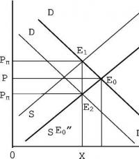
Breaking load is often used to evaluate the wear kinetics of fabrics. In Fig. Figure 3 shows typical curves of changes in the breaking load of fabrics during the operation of the latter. As you can see, a high initial value of the breaking load does not yet determine the behavior of the fabric in the sock. One fabric (curve) had a greater initial breaking load than the other fabric (curve). But during operation, the first fabric wears out faster, and after a certain period its breaking load is less than that of the second fabric. In this regard, the fabric to which the curve corresponds has a shorter wear life.
Elongation at break (absolute) is the difference between the length of the sample at the moment of rupture and its clamping length before rupture.
Fabrics with high elongation at break, such as wool and synthetic fibers, usually have good elasticity, wrinkle resistance, abrasion resistance, etc.
Like breaking load, elongation at break largely depends on the quality of the raw material from which the fabric is made. At the same breaking load, the best fabric in terms of mechanical properties is considered to be the one that has a higher elongation at break. The mechanical properties of the fabric to which the curve / corresponds are better than those of the fabric to which the curve corresponds, since due to the greater elongation at break, the work of rupture (shaded area) is greater. Since the work of rupture characterizes the amount of energy that must be expended to break the material, the first fabric can be considered more “strong” than the second.
The breaking load and elongation at break of fabrics are determined by testing three test strips for the warp and four for the weft. The dimensions of the test strips are indicated in table. 6. If disagreements arise, test strips measuring 50x100 mm for woolen fabrics and 50x200 mm for all other fabrics are tested. Blanks for test strips are cut from a fabric sample using special metal templates. The width of the workpieces is 30 or 60 mm, the length should be 150 mm greater than the clamping length. Longitudinal threads are removed from both sides of the workpieces until the working width of the test strips of fabric becomes equal to 25 or 50 mm.
According to GOST 3813-72, test strips are subjected to stretching to failure on three types of tensile machines: with a variable rate of increase in load and deformation, with a constant rate of increase in load, and with a constant rate of deformation. The difference between these machines lies in the nature of the loading or deformation of the material being tested.
In Fig. 5 shows diagrams of load and deformation obtained on tensile testing machines various types. Machines of the second and third types are considered more advanced, since the nature of the increase in load or deformation of the materials tested on them does not depend on the characteristics of the mechanical properties of the latter. This allows for a more accurate comparison mechanical properties various materials. Machines of the first type lack this advantage. For example, a shows diagrams of the increase in load and deformation of two tissues. Despite the fact that the final test results of these fabrics (breaking load and elongation at break) are the same, it cannot be said that the mechanical properties of the fabrics are the same. At the same time, machines of the first type are simpler to design and operate.
A test strip of fabric is tucked into the clamps. The clamp is connected to a lever (pendulum). Therefore, the machines in question are sometimes called tensile testing machines with a pendulum force meter, or pendulum-type tensile testing machines. The clamp can be lowered at a constant speed; it receives movement from some kind of drive, usually electric. As the lower clamp moves, force is transferred through the sample to the upper clamp, and the load arm begins to deviate to the left. The load on the sample increases in proportion to the increase in the angle cp. At the moment of destruction of the test strip, the arrow of lever 2 stops and on the scale / shows the value of the breaking load. And on scale 3, the elongation at break is determined.
By changing the load on lever 2, you can change the range of loads obtained during testing.
In the USSR, the RT-250M tensile testing machine with a pendulum force meter is commercially produced, having a load range from 0 to 50 and from 0 to 250 kgf. We note here that the load scale of the tensile testing machine should be selected so that the average breaking load of the test sample is within 20-80% of the maximum scale value.
According to GOST 3813-72, when inserting test strips into the clamps of a tensile testing machine, they are given pre-tension by hanging special weights from the lower end of the test strip. The size of the pre-tension weights is selected depending on the size of the test strip and the surface density of the fabric being tested.
When testing, the lowering speed of the lower clamp of the tensile testing machine must be such that the average duration of stretching of the test strip before failure corresponds to 30 ± 5 s for fabrics with an elongation of less than 150% and 60 ± 15 s for fabrics with an elongation of 150% or more.
The arithmetic mean of all primary results is taken as the final result when determining the breaking load and elongation at break.
Tearing load is the force (kgf, N) required to break a specially cut test strip of fabric. This load characterizes the ability of tissues to withstand force, which is concentrated in a relatively small area, for example, during tears, when rigidly securing the edge of the fabric, etc.
When determining the tearing load (GOST 17922-72), test strips cut from the sample - three with a transverse arrangement of warp threads and four with a transverse arrangement of weft threads - are marked according to the diagram. An incision is made along the line and the resulting tabs are inserted into the clamps of the tensile testing machine along lines AB and AC. The distance between the clamps is set to 100 mm, the lowering speed of the lower clamp is 100 ± 10 mm/min. When the lower clamp moves, the load is transferred through the longitudinal threads to the transverse threads and they tear in the direction of the cut. The test strip is broken to line aa. The tearing load of the fabric is calculated as the arithmetic mean of the results of the primary tests for the warp and weft.
Typically, the tearing load of tissues is much less than the breaking load. For example, if according to GOST 5067-74 the tearing load of silk and semi-silk dress and suit fabrics is at least 0.8 kgf, then the breaking load is at least 20 kgf.
For cotton and silk fabrics with pile, the standards should standardize the strength of pile fixing.
The strength of the pile is characterized by the force required to pull out one lint from the pile fabric. When determining this indicator (GOST 3815.3 -77), five strips measuring 20X100 mm are cut from the sample along the base. Another strip of fabric 20 mm wide and 250 mm long is sewn to both ends of each strip. By folding the resulting tape in half, a number of fibers are isolated from the test strip of fabric, which are clamped in the upper clamp of a tensile testing machine for testing a single thread. The lower part of the tape under a tension of 25 gf is inserted into the lower clamp of the tensile testing machine. The distance between the clamps is 200 mm, the lowering speed of the lower clamp is 200 mm/min. At the moment of complete pulling out of the villi, the readings of the load scale are noted. The fibers remaining in the upper clamp are counted, after which the force required to pull out one fiber is determined.
When stretching textile fabrics until they break, the following half-cycle breaking characteristics can be determined: breaking load, absolute elongation at break, relative elongation at break.
(H) – the greatest force the test strip can withstand before breaking. To compare the breaking load of textile fabrics of different weights, use specific breaking load (kN m/kg), calculated by the formula
 ,
,
Elongation at break
 (%) – increment in the length of the stretched test strip at the moment of rupture:
 ,
,
Breaking stress (Pa)
 ,
,
This characteristic is necessary to compare the tension of the structural elements of the canvases.
The breaking load of fabrics is determined according to GOST 3813 by testing various types of test strips cut from a sample on tensile testing machines.
Tensile testing machines for testing textile fabrics, depending on the parameter set and maintained constant when loading single samples, are divided into three groups: with a constant lowering speed of the lower clamp; with a constant rate of sample deformation; with a constant rate of increase in force per sample.
Before testing, elementary samples measuring 50 × 200 mm were marked so that one elementary sample was not a continuation of another. The first elementary test in the direction of the warp was marked at a distance of at least 50 mm from the edge of the fabric. Elementary samples in the direction of the weft were marked at a distance of at least 50 mm from the edge of the point sample, distributing them sequentially along the length.
To obtain the working width of an elementary sample, threads in the longitudinal directions were removed from both sides until the load-bearing width became equal to 50 mm.
Elementary samples were clamped in the clamps of a tensile testing machine with a pre-tension of 0.50 kgf.
When filling an elementary sample into the clamp of the machine, one of its ends was passed into the upper clamp and clamped. After this, the other end of the elementary sample was inserted into the lower clamp and pre-tensioned. The upper clamp was loosened and, under the action of a load or pre-tension mechanism, the elementary sample was allowed to fall slightly and the upper and then the lower clamp were firmly clamped.
Indicators of breaking load and elongation at break were taken from the corresponding scales of the tensile testing machine after breaking the elementary sample.
Per indicator breaking load of the sample, the arithmetic mean of the results of 3-4 measurements was taken for the warp and weft.
For fabric 1 (art. 061376):
Based on:
R p1=272.5 N;
R p2=304.4 N;
R p3=280.0 N.
R p1=286.8 N;
R p2=263.6 N;
R p3=272.5 N;
R p4=268.5 N;
Per indicator absolute elongation at break the arithmetic mean of the results of 3-4 measurements was taken.
Based on:
l p 1 =9.67 mm;
l p 2 =9.19 mm;
l p 3 = 9.38 mm.
l p = mm.
mm.
l p 1 =12.11 mm;
l p 2 =14.71 mm;
l p 3 =13.10 mm;
l p 4 =13.42 mm.
l p= mm.
Elongation at break R :
Based on:


Based on:
Breaking stress
 :
:
Based on:
 Pa;
Pa;
 Pa.
Pa.
The results of other calculations of breaking load, absolute and relative elongation at break, specific breaking load and breaking stress are given in Table. 3.16.
|
Table 3.16 |
||||||||||
|
Tear characteristics of fabrics |
||||||||||
|
Fabric name | Wed, N
Absolute elongation at break |
Elongation at break | ABOUT, kN m/kg
Breaking stress
|
|||||||
|
based on |
based on |
based on |
based on |
based on | ||||||
|
(art. 061376) | ||||||||||
|
(art. 06159) | ||||||||||
|
(art. 06148) | ||||||||||
|
(art. 06147) | ||||||||||
|
(art. 06146) | ||||||||||
 , mm
, mm ,
%
,
% , Pa
, PaLECTURE No. 11
1. The purpose and essence of the method.
2. Determination of coefficients that take into account the proportion of warp and weft threads in the fabric.
3. Determination of the conditional length of the fabric.
4. determination of the number of warp and weft threads in the fabric.
5. Improving the design method of Prof. O.S. Kutepov.
6. The procedure for designing fabric for a given tensile strength using the amendments of Prof. O.S. Kutepova.
The method was called “Engineer A. A. Sinitsyn’s Method” after the author who proposed it in 1932. This method was later supplemented by Prof. O.S. Kutepov. It is used in cases where it is necessary to design a fabric with a given tensile strength of the fabric strip along the warp and weft.
The purpose of this The method is to determine the number of warp and weft threads per 10 cm of fabric while maintaining the surface density of the fabric and the thickness of the threads for a given breaking load of a strip of fabric.
To solve this problem, A. A. Sinitsyn uses the concept breaking length of the fabric along the warp and weft (;). The physical meaning of the breaking length of a strip of fabric expresses the length of the strip of fabric (in km) at which the fabric will break under the influence of its own mass.
For design, a standard fabric is used that has the following data:
Surface density of fabric (mm 2);
) and by duck ();The number of warp threads () and the number of weft threads () per 10 cm of gray fabric;
Linear density of warp () and weft ().
The breaking load of a fabric strip is determined taking into account the percentage of use of warp and weft threads using the following formulas.
The percentage of warp threads used in the fabric is:
The percentage of weft threads used in fabric is:
where is the breaking load of the warp and weft yarn, cN/tex.
Knowing the tensile load of a strip of fabric along the warp and weft and the surface density of the fabric, A.A. Sinitsyn determines the breaking length of a strip of fabric using the following formulas.
Breaking length of fabric strip along the base:
where 20 is the conversion factor for a strip of fabric measuring 50-200 cm.
When a strip of fabric is torn along the warp, the weft plays a passive role and therefore it slightly changes the strength of the strip of fabric along the warp. Exactly the same phenomenon is observed with warp threads when a strip of fabric is torn at the weft. Therefore A.A. Sinitsin introduced the concept conditional breaking length of the fabric along the warp and weft, the threads of which bear the main influence of the breaking load.
Conditional breaking length of fabric based on:
Conditional breaking length of fabric by weft:
Subsequent calculations boil down to determining the coefficients α and β, which determine the proportion of warp and weft threads in the surface density of the fabric.
Provided that α + β = 1, we can write that the mass of warp threads in 1m2 of fabric will be equal to
Mm 2 = α Mm 2 + β Mm 2,
where the mass of warp threads is - α ;
the mass of weft threads is - β .·
Let us determine the coefficients α and β for the reference fabric. To do this, we determine the ratio of the masses of the warp and weft threads - M o / M y, equal to:
| (16.4) |
where is the fabric shrinkage in finishing, %.
Equating the left and right parts of the resulting expression, having previously replaced the values of the mass of the warp threads with the expression M o =α and the mass of weft threads is the expression M y = β , and adding the equation α + β = 1 we obtain a system of equations of the form:
Having determined the coefficients α and β, the conditional breaking length along the warp and weft is determined.
Knowing the conditional breaking length based on the warp and weft of the standard fabric, Sinitsyn proceeds to calculating the designed fabric. In this case, the following assumption is introduced: the conditional breaking length for the reference fabric and the designed fabric remains constant, i.e. And .
In this case, we can write that the conditional breaking length of the reference fabric along the base is equal to:
where , is the breaking load of the strip of fabric being designed, cN;
α′, β′ – the share of warp and weft yarn in the surface density of the designed fabric.
Sinitsyn transforms the above equations to the form
from which determines the proportion of warp threads in the designed fabric.
The proportion of warp threads in the designed fabric is equal to:
from which it finds the values of β¢ and α¢.
The proportion of weft threads in the designed fabric is:
Having determined the expressions for α" and β", by analogy with equation (), we compose an equation of the form
The base density in the designed fabric is equal to
where is the density of the warp and weft in the designed fabric.
In this equation there are two unknowns, Ro and Ru. To solve this equation, A.A. Sinitsyn used the empirical method proposed by Brierley. However, the Brierley method is applicable to a very narrow range of fabrics. These are mainly fabrics of the following weaves: plain, satin weave and matting. For fabrics of other weaves, the engineering method. A. A. Sinitsyn cannot be used. Due to these limitations and complexity in calculations, Sinitsin’s method in this presentation has not found wide application.
However, it can be used for other weaves of single-layer fabrics by applying the thread density coefficients in the fabric introduced by Prof. O.S. Kutepov. In this case, the designed fabric is conditionally equated to a fabric with a square structure, after which the proportion of warp and weft threads is recalculated in accordance with the specified value of the coefficients α and β. In this case, the design order is as follows.