Scalar and vector control of asynchronous motors. Principles of vector control of an asynchronous motor What is vector control
For getting High Quality To control electric drives in static and dynamic (transient) modes, it is necessary to be able to quickly and directly control the engine torque.
The torque of any motor in each period of time is determined by the magnitude (amplitude) and phase of two torque-generating components: current and magnetic flux. In IM, the currents and flux linkages of the stator and rotor rotate at the same speeds, have different, time-varying phase parameters and are not subject to direct measurement and control. The available controlled variable in the IM is the stator current, which has components that form the magnetic flux and torque. The phase orientation of these two components can only be achieved by an external control device, which is what gives rise to the term “vector control”.
In the structure of the electric drive, the motor is considered as an electromechanical EMF converter in the form of an idealized motor. Its rotor does not have mass and mechanical energy, has no mechanical energy losses and is rigidly connected to the real physical rotor, which belongs to the mechanical part of the electric drive. Such a motor can be represented by an electromechanical multi-terminal network containing n pairs of electrical leads according to the number of n windings, and one pair of mechanical leads (see Figure 2). At mechanical terminals as a result of electromechanical conversion (EMT) of energy at speed w the electromagnetic torque M develops. The torque M is the output value of the EMF and the input value for the mechanical part of the electric drive. Speed w is determined by the conditions of movement of the mechanical part, but for EMF it can be considered as an independent variable. Mechanical Variables M And w connect EMF with the mechanical part into a single interconnected system. All processes in the engine are described by a system of electrical equilibrium equations (the number of equations is equal to the number of windings) and the equation of electromechanical energy conversion. To do this, in the theory of electric power plants, a two-phase model of a generalized electric machine is used (see Figure 1), to which absolutely all types and types of electrical machines are reduced:
Figure 1 – Model of generalized EMF.
α, β – fixed stator axes; d, q– rotating axes of the rotor; φ – rotor rotation angle; — angular speed of the rotor;
Electrical equilibrium equation i- windings:
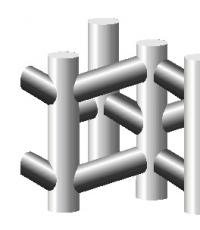
Figure 2 – Vector control circuit
The vector control circuit consists of three main functional parts:
BRP– block of variable regulators;
BVP– variable calculation block;
BZP– block for setting variables;
At the entrance BRP speed and flow command signals are received, as well as feedback signals (from the output BVP) – field-oriented values of the components of the stator current, rotor flux linkage, and speed. BRP contains a set of flux, torque, and current regulators, at the output of which field-oriented signals for setting the components of the stator current are also generated.
BZP carries out phase and coordinate transformations of the defining d – q variables into the three-phase control signal system PWM AIN. Block BVP calculates the current values of amplitude and phase parameters d – q IM variables, carrying out phase and coordinate transformations of real three-phase IM current and voltage signals coming from the outputs of the corresponding sensors.
Coordinate transformations carried out by the block BVP, consist in the transition from the real coordinates of the three-phase system of the IM stator with the axes d,q(transformation 3 → 2). Block BZP carries out inverse coordinate transformations (2 → 3), from d— q To a, b, c.
Phase transformations in these blocks provide binding of phase parameters of variables in two coordinate systems.
The reliability, cost and quality of ED characteristics are affected by the number of measured parameters and measurement accuracy. For vector control of blood pressure, it is necessary to measure at least two of the four variables available for measurement:
- IM stator currents;
- Voltage at the IM terminals;
- Angular speed of the IM rotor;
- Angular position of the IM rotor;
Vector control allows you to obtain the maximum cos φ IM at almost any time, at any position of the rotor relative to the stator, at any angular speed and load on the machine. This, in turn, significantly increases the efficiency and torque. machine, which, in this case, practically does not depend on the angular velocity of the engine.
Dmitry Levkin
Scalar control(frequency) - a method of controlling brushless alternating current, which consists of maintaining a constant voltage/frequency ratio (V/Hz) throughout the entire operating speed range, while only controlling the magnitude and frequency of the supply voltage.
The V/Hz ratio is calculated based on the rating (and frequency) of the AC motor being monitored. By keeping the V/Hz ratio constant, we can maintain a relatively constant magnetic flux in the motor gap. If the V/Hz ratio increases then the motor becomes overexcited and vice versa if the ratio decreases the motor is in an underexcited state.

Changing the motor supply voltage with scalar control
At low speeds it is necessary to compensate for the voltage drop across the stator resistance, so the V/Hz ratio at low speeds is set higher than the nominal value. The scalar control method is most widely used to control asynchronous electric motors.
As applied to asynchronous motors
In the scalar control method, the speed is controlled by setting the stator voltage and frequency so that the magnetic field in the gap is maintained at the desired value. To maintain a constant magnetic field in the gap, the V/Hz ratio must be constant at different speeds.

As the speed increases, the stator supply voltage must also increase proportionally. However, the synchronous frequency of an asynchronous motor is not equal to the shaft speed, but depends on the load. Thus, a scalar open-loop control system cannot accurately control speed when a load is present. To solve this problem, speed feedback, and therefore slip compensation, can be added to the system.

Disadvantages of Scalar Control
- Method scalar control relatively simple to implement, but has several significant disadvantages:
- firstly, if a speed sensor is not installed, you cannot control the shaft rotation speed, since it depends on the load (the presence of a speed sensor solves this problem), and in the case of a change in load, you can completely lose control;
- secondly, it cannot be controlled. Of course, this problem can be solved using a torque sensor, but the cost of installing it is very high, and will most likely be higher than the electric drive itself. In this case, torque control will be very inertial;
- it is also impossible to control torque and speed at the same time.
Scalar control is sufficient for most tasks in which an electric drive is used with an engine speed control range of up to 1:10.
When maximum speed is required, the ability to regulate over a wide speed range and the ability to control the torque of the electric motor is used.
In order to regulate the angular speed of rotation of the rotor, as well as the torque on the shaft of modern brushless motors, either vector or scalar control of the electric drive is used.
Scalar control of an asynchronous motor has become most widespread, when to control, for example, the rotation speed of a fan or pump, it is enough to keep the rotor rotation speed constant; for this, a feedback signal from a pressure sensor or a speed sensor is sufficient.
The principle of scalar control is simple: the amplitude of the supply voltage is a function of frequency, and the ratio of voltage to frequency is approximately constant.
The specific type of this dependence is associated with the load on the shaft, but the principle remains the same: we increase the frequency, and the voltage increases proportionally depending on the load characteristics of a given motor.
As a result, the magnetic flux in the gap between the rotor and stator is maintained almost constant. If the voltage-to-frequency ratio deviates from the nominal one for a given motor, then the motor will either be overexcited or underexcited, which will lead to losses in the motor and disruptions in the working process.

Thus, scalar control makes it possible to achieve an almost constant torque on the shaft in the operating frequency range, regardless of frequency, however, at low speeds the torque still decreases (to prevent this from happening, it is necessary to increase the voltage-to-frequency ratio), so for each motor there is a strictly defined operating scalar control range.
In addition, it is impossible to build a scalar speed control system without a speed sensor mounted on the shaft, because the load greatly affects the lag of the actual rotor rotation speed from the supply voltage frequency. But even with a speed sensor, with scalar control it will not be possible to regulate the torque with high accuracy (at least in a way that would be economically feasible).
This is where the shortcomings of scalar control lie, explaining the relative small number of areas of its application, limited mainly to conventional asynchronous motors, where the dependence of slip on load is not critical.

To get rid of these shortcomings, back in 1971, Siemens engineers proposed using vector motor control, in which control is carried out with feedback on the magnitude of the magnetic flux. The first vector control systems contained flux sensors in the motors.

Today, the approach to this method is somewhat different: a mathematical model of the engine allows you to calculate the rotor rotation speed and shaft torque depending on the current phase currents (on the frequency and magnitude of the currents in the stator windings).
This more progressive approach makes it possible to independently and almost inertia-free regulate both the torque on the shaft and the speed of rotation of the shaft under load, because the control process also takes into account the phases of the currents.
Some more precise vector control systems are equipped with speed feedback circuits, and control systems without speed sensors are called sensorless.
So, depending on the area of application of a particular electric drive, its vector control system will have its own characteristics and its own degree of adjustment accuracy.
When the requirements for speed control accuracy allow a deviation of up to 1.5%, and the adjustment range does not exceed 1 to 100, then a sensorless system is quite suitable. If speed control accuracy is required with a deviation of no more than 0.2%, and the range is reduced to 1 in 10,000, then feedback from the speed sensor on the shaft is necessary. The presence of a speed sensor in vector control systems allows precise torque control even at low frequencies up to 1 Hz.

So, vector control provides the following advantages. High precision control of the rotor rotation speed (and without a speed sensor on it) even under conditions of dynamically changing load on the shaft, and there will be no jerks. Smooth and even shaft rotation at low speeds. High efficiency due to low losses under conditions of optimal supply voltage characteristics.
Vector control is not without its drawbacks. Complexity of computational operations. The need to set initial data (variable drive parameters).
For a group electric drive, vector control is fundamentally unsuitable; scalar control is better suited here.
To implement the ability to regulate torque and speed, modern electric drives use the following frequency control methods, such as:
- Vector;
- Scalar.
The most widespread are asynchronous electric drives with scalar control. It is used in drives of compressors, fans, pumps and other mechanisms in which it is necessary to maintain at a certain level either the rotation speed of the electric motor shaft (a speed sensor is used), or some technological parameter (for example, pressure in a pipeline, using an appropriate sensor).
The operating principle of scalar control of an asynchronous motor is that the amplitude and frequency of the supply voltage change according to the law U/f^n = const, where n>=1. How this dependence will look in a particular case depends on the requirements imposed by the load on the electric drive. As a rule, frequency acts as an independent influence, and the voltage at a certain frequency is determined by the type of mechanical characteristic, as well as the values of the critical and starting torques. Thanks to scalar control, a constant overload capacity of an asynchronous motor is ensured, independent of the voltage frequency, and yet at fairly low frequencies a significant reduction in the torque developed by the motor can occur. The maximum value of the scalar control range at which it is possible to regulate the rotation speed of the electric motor rotor without losing the moment of resistance does not exceed 1:10.
Scalar control of an induction motor is quite simple to implement, but there are still two significant drawbacks. Firstly, if a speed sensor is not installed on the shaft, then it is impossible to regulate the value of the shaft rotation speed, since it depends on the load acting on the electric drive. Installing a speed sensor easily solves this problem, but another significant drawback remains - the inability to regulate the torque value on the motor shaft. You can, of course, install a torque sensor, but the cost of such sensors, as a rule, exceeds the cost of the electric drive itself. Moreover, even if you install a torque control sensor, the process of controlling this very torque will turn out to be incredibly inertial. Another “but” - scalar control of an asynchronous motor is characterized by the fact that it is impossible to simultaneously regulate speed and torque, so it is necessary to regulate the value that is most important at a given time due to the conditions of the technological process.
In order to eliminate the shortcomings of scalar motor control, back in the 71st year of the last century, SIEMENS proposed the introduction of a vector motor control method. The first electric drives with vector control used motors that had built-in flow sensors, which significantly limited the scope of such drives.
The control system of modern electric drives contains a mathematical model of the engine, which allows one to calculate the rotation speed and shaft torque. Moreover, only motor stator phase current sensors are installed as necessary sensors. The specially designed structure of the control system ensures independence and virtually inertia-free control of the main parameters - shaft torque and shaft rotation speed.
To date, the following vector control systems for asynchronous motors have been formed:
- Sensorless – there is no speed sensor on the motor shaft,
- Systems with speed feedback.
The use of vector control methods depends on the application of the electric drive. If the speed measurement range does not exceed 1:100, and the accuracy requirements vary within ±1.5%, then a sensorless control system is used. If the speed measurement is carried out in the range of values reaching 1: 10000 or more, and the level of accuracy must be quite high (±0.2% at speeds below 1 Hz), or it is necessary to position the shaft or control the torque on the shaft at low speeds , then a system with speed feedback is used.
Advantages of the vector method of controlling an asynchronous motor:
- High level accuracy when regulating the shaft rotation speed, despite the possible absence of a speed sensor,
- The engine rotates at low frequencies without jerking, smoothly,
- If a speed sensor is installed, then the nominal value of the torque on the shaft can be achieved even at zero speed value,
- Quick response to possible load changes - sudden load surges have virtually no effect on the speed of the electric drive,
- High level of motor efficiency due to reduced losses due to magnetization and heating.
Despite the obvious advantages, the vector control method also has certain disadvantages - greater complexity of calculations; knowledge of the motor parameters is required for operation. In addition, fluctuations in the speed value at a constant load are much greater than with the scalar control method. By the way, there are areas where electric drives are used exclusively with a scalar control method. For example, a group electric drive in which one converter powers several motors.